pdf格式的文档: 下载
下表显示了与本手册兼容的 BSP:
适用BSP |
BSP 发布类型 |
Yocto Version |
BSP发布日期 |
BSP 状态 |
|---|---|---|---|---|
BSP-Yocto-Ampliphy-AM62Lx-ALPHA2 |
Alpha |
Scarthgap |
2025/07/10 |
已发布 |
本手册指导您完成BSP包的安装、编译和烧写,并描述如何使用 phyFLEX-AM62L FPSC Kit 的硬件接口。本手册还包括如何从源码编译内核、u-boot镜像。本手册包含需要在PC(Linux操作系统)上执行的指令。
备注
This document contains code examples that describe the communication with the
board over the serial shell. The code examples lines begin with host:~$,
target:~$ or u-boot=>. This describes where the commands are to be
executed. Only after these keywords must the actual command be copied.
1. PHYTEC 文档
PHYTEC provides a variety of hardware and software documentation for all of its products. This includes any or all of the following:
- QS Guide
A short guide on how to set up and boot a phyCORE based board.
- Hardware Manual
A detailed description of the System-on-Module and accompanying carrierboard.
- Yocto Guide
A comprehensive guide for the Yocto version the phyCORE uses. This guide contains an overview of Yocto; introducing, installing, and customizing the PHYTEC BSP; how to work with programs like Poky and Bitbake; and much more.
- BSP 手册
A manual specific to the BSP version of the phyCORE. Information such as how to build the BSP, booting, updating software, device tree, and accessing peripherals can be found here.
- Development Environment Guide
This guide shows how to work with the Virtual Machine (VM) Host PHYTEC has developed and prepared to run various Development Environments. There are detailed step-by-step instructions for Eclipse and Qt Creator, which are included in the VM. There are instructions for running demo projects for these programs on a phyCORE product as well. Information on how to build a Linux host PC yourself is also a part of this guide.
- Pin Muxing Table
phyCORE SOMs have an accompanying pin table (in Excel format). This table will show the complete default signal path, from the processor to the carrier board. The default device tree muxing option will also be included. This gives a developer all the information needed in one location to make muxing changes and design options when developing a specialized carrier board or adapting a PHYTEC phyCORE SOM to an application.
除了这些标准手册和指南之外,PHYTEC 还将提供产品变更通知、应用说明和技术说明。这些文档将根据具体案例进行针对性提供。大部分文档都可以在我们产品的 https://www.phytec.de/produkte/system-on-modules/phyflex-am62lx-fpsc/#downloads/ 中找到。
1.1. 支持的硬件
在我们的网页上,您可以查看适用于BSP版本 BSP-Yocto-Ampliphy-AM62Lx-ALPHA2 的所有Machine及其对应的Article Numbers(产品型号): 网页.
如果您在“Supported Machines”一栏选择了特定的 Machine Name ,您可以查看该machine下可用的 Article Numbers 以及硬件信息的简短描述。如果您只有硬件的 Article Numbers ,您可以将 Machine Name 下拉菜单留空,仅选择您的 Article Numbers 。现在,它应该会显示您特定硬件所需的 Machine Name
1.1.1. Libra FPSC 器件
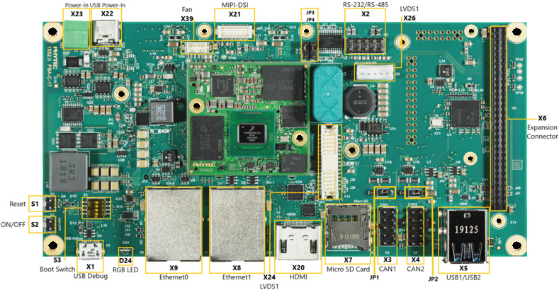
Libra 器件(顶部)
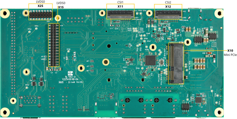
Libra 器件(底部)
2. 开始使用
The phyFLEX-AM62L FPSC Kit is shipped with a pre-flashed SD card. It contains the phytec-qt6demo-image and can be used directly as a boot source. The e.MMC is programmed with only a U-Boot by default. You can get all sources from the BSP downloads page. This chapter explains how to flash a BSP image to SD card and how to start the board.
There are several ways to flash an image to SD card or even e.MMC. Most notably
using simple, sequential writing with the Linux command line tool dd. An
alternative way is to use PHYTEC's system initialization program called
partup, which makes it especially easy to
format more complex systems. You can get prebuilt Linux binaries of partup from its release page. Also read
partup's README for installation
instructions.
2.1. 下载镜像
The image contains all necessary files and makes sure partitions and any raw
data are correctly written. Both the partup package and the WIC image, which can
be flashed using dd, can be downloaded from our BSP downloads page.
Note that you can find different image versions and variants on our download server. The images are located on the server by folders per "BSP-Version", "Distro-Name" and "Machine-Name".
Example to download a partup package and a WIC image from the download server:
host:~$ wget https://download.phytec.de/Software/Linux/BSP-Yocto-AM62Lx/BSP-Yocto-Ampliphy-AM62Lx-ALPHA2/images/ampliphy-vendor/am62lxx-libra-fpsc-1/phytec-qt6demo-image-am62lxx-libra-fpsc-1.rootfs.partup
host:~$ wget https://download.phytec.de/Software/Linux/BSP-Yocto-AM62Lx/BSP-Yocto-Ampliphy-AM62Lx-ALPHA2/images/ampliphy-vendor/am62lxx-libra-fpsc-1/phytec-qt6demo-image-am62lxx-libra-fpsc-1.rootfs.wic.xz
备注
For e.MMC, more complex partitioning schemes or even just large images, we
recommend using the partup package, as it is faster in writing than dd
and allows for a more flexible configuration of the target flash device.
2.2. 将镜像写入SD卡
警告
要创建SD卡启动盘,必须要拥有Linux PC上的root权限。在选择烧写设备时请务必小心!所选设备上的所有文件将在命令执行后立即被擦除,而且擦除前不会有任何进一步的确认!
选择错误的设备可能会导致 数据丢失 ,例如,可能会擦除您当前所在PC上的系统!
2.2.1. 寻找正确的设备
要创建SD卡启动盘,首先要找到PC上您SD卡对应的正确设备名称。在开始将镜像复制到SD卡之前,请卸载任何已挂载的分区。
为了获取正确的设备名称,请移除您的SD卡并执行:
host:~$ lsblk现在插入你的SD卡,然后再次执行命令:
host:~$ lsblk比较两个输出,以获取第二个输出中的新设备名称。这些是SD卡的设备名称(如果SD卡已格式化,则包括设备名称和对应的分区)。
为了验证找到的设备名称的最终正确性,请执行命令
sudo dmesg。在其输出的最后几行中,您应该也能找到设备名称,例如/dev/sde或/dev/mmcblk0(具体取决于您的系统)。
或者,您可以使用图形化的程序,例如 GNOME Disks 或 KDE Partition Manager 来找到正确的设备。
现在您已经得到了正确的设备名称,例如 /dev/sde,如果SD卡曾格式化过,需要确认已取消其分区的挂载,您可以在输出中看到带有附加了数字的设备名称(例如 /dev/sde1),它们是SD卡的分区。一些Linux发行版系统在设备插入时会自动挂载分区。在写入之前,必须卸载这些分区,以避免数据损坏。
卸载所有这些分区,例如:
host:~$ sudo umount /dev/sde1
host:~$ sudo umount /dev/sde2
Now, the SD card is ready to be flashed with an image, using either partup,
dd or bmaptool.
2.2.2. Using bmaptool
One way to prepare an SD card is using
bmaptool. Yocto
automatically creates a block map file (<IMAGENAME>-<MACHINE>.wic.bmap) for
the WIC image that describes the image content and includes checksums for data
integrity. bmaptool is packaged by various Linux distributions. For
Debian-based systems install it by issuing:
host:~$ sudo apt install bmap-tools
通过以下命令将WIC镜像烧写到SD卡:
host:~$ bmaptool copy phytec-qt6demo-image-am62lxx-libra-fpsc-1?(.rootfs).wic?(.xz) /dev/<your_device>
将 <your_device> 替换为您之前找到的SD卡设备名称,并确保将文件 <IMAGENAME>-<MACHINE>.wic.bmap 与WIC镜像文件放在一起,以便bmaptool知道哪些块需要写入,哪些块需要跳过。
警告
bmaptool 仅擦写SD卡上镜像数据所在的区域。这意味着在写入新的镜像后,之前写入的旧U-Boot环境变量可能仍然可用。
2.2.3. 使用partup
使用partup烧写SD卡只需一个命令:
host:~$ sudo partup install phytec-qt6demo-image-am62lxx-libra-fpsc-1?(.rootfs).partup /dev/<your_device>
确保将 <your_device> 替换为您之前找到的设备名称。
关于partup的进一步使用说明,请参阅其 官方文档 。
警告
使用resize2fs版本1.46.6及更早版本的PC系统(例如Ubuntu 22.04)无法烧写在Mickledore以及更新的yocto版本上创建的partup软件包。这个是因为resize2fs新增了默认选项而导致的兼容性问题。有关详细信息,请参阅 release notes 。
备注
partup 具有清除eMMC user区域中特定区域的功能,我们提供的partup程序中用该功能擦除U-Boot环境变量。这是 bmaptool 工具所无法完成的一点,如前一部分所提到的。
partup相较于其他烧写工具的一个主要优势是,它可以配置MMC的特定部分,比如他可以直接写入eMMCboot分区,无需调用其他命令。
2.2.4. 使用 dd
在卸载所有SD卡的挂载分区后,您可以烧写SD卡。
一些PHYTEC BSP会生成未压缩的镜像(文件名扩展名为*.wic),而另一些则生成压缩的镜像(文件名扩展名为*.wic.xz)。
要写入未压缩的镜像(*.wic),请使用以下命令:
host:~$ sudo dd if=phytec-qt6demo-image-am62lxx-libra-fpsc-1?(.rootfs).wic of=/dev/<your_device> bs=1M conv=fsync status=progress
或者要写入压缩后的镜像(*.wic.xz),请使用以下命令:
host:~$ xzcat phytec-qt6demo-image-am62lxx-libra-fpsc-1?(.rootfs).wic.xz | sudo dd of=/dev/<your_device> bs=1M conv=fsync status=progress
再次确保将 <your_device> 替换为之前找到的设备名称。
参数 conv=fsync 强制在 dd 返回之前对设备进行sync操作。这确保所有数据块都已写入SD卡,而没有任何数据缓存在内存中。参数 status=progress 将打印出进度信息。
2.3. 首次启动
要从SD卡启动, bootmode switch (S1) 需要设置为以下位置:

插入SD卡
Connect the target and the host with USB-C on (X14) debug USB
给开发板通电
3. 编译BSP
本节将指导您使用Yocto和phyLinux脚本进行 AM62L BSP的编译。更多有关phytec meta-layer和Yocto的信息,请访问: Yocto Reference Manual (scarthgap) 。
3.1. 基本设置
如果您从未在您的主机上使用Yocto编译过Phytec BSP,您应查看 Yocto Reference Manual (scarthgap) 中的BSP Workspace安装一节。
3.2. 下载BSP
There are two ways to get the BSP sources. You can download the complete BSP sources from our BSP downloads page; or you can fetch and build it yourself with Yocto. This is particularly useful if you want to make customizations.
The phyLinux script is a basic management tool for PHYTEC Yocto BSP releases written in Python. It is mainly a helper to get started with the BSP sources structure.
创建一个新的项目文件夹,获取phyLinux脚本,并赋予脚本具备可执行权限:
host:~$ mkdir ~/yocto
host:~$ cd yocto/
host:~/yocto$ wget https://download.phytec.de/Software/Linux/Yocto/Tools/phyLinux
host:~/yocto$ chmod +x phyLinux
警告
我们需要一个空的项目文件夹,phyLinux首先会清理当前所在的工作目录。从一个不为空的目录下调用phyLinux将会产生告警。
运行phyLinux:
host:~/yocto$ ./phyLinux init
备注
在首次初始化时,phyLinux脚本会要求您在
/usr/local/bin目录中安装Repo工具。During the execution of the init command, you need to choose your processor platform (SoC), PHYTEC's BSP release number, and the hardware (MACHINE) you are working on.
备注
If you cannot identify your board with the information given in the selector, have a look at the invoice for the product. And have a look at the webpage of our BSP.
也可以通过命令行参数直接传递这些信息:
host:~/yocto$ DISTRO=ampliphy-vendor MACHINE=am62lxx-libra-fpsc-1 ./phyLinux init -p am62l-fpsc -r BSP-Yocto-Ampliphy-AM62Lx-ALPHA2
After the execution of the init command, phyLinux will print a few important notes. For example, it will print your git identity, SOC and BSP release which was selected as well as information for the next steps in the build process.
3.2.1. 开始构建
设置Shell环境变量:
host:~/yocto$ source sources/poky/oe-init-build-env
备注
在每次打开新的用于编译的shell时,都需要先执行这一步骤。
当前的工作目录会变更为 build/。
编译您的镜像:
host:~/yocto/build$ bitbake phytec-qt6demo-image
备注
对于第一次编译,我们建议从我们的较小的非图形化镜像phytec-headless-image开始,以查看一切是否正常工作。
host:~/yocto/build$ bitbake phytec-headless-image
第一次构建过程在现代的Intel Core i7处理器上大约需要40分钟。后续的构建将使用本次编译产生的缓存,大约需要3分钟。
3.2.2. BSP镜像
所有由Bitbake生成的镜像都放在 ~/yocto/build/deploy*/images/<machine> 。例如以下列表是 am62lxx-libra-fpsc-1 machine生成的所有文件:
u-boot.img: U-Boot bootloader image
oftree: 默认内核设备树
ti-boot3.bin: First stage bootloader (R5 SPL)
tispl.bin: Secondary program loader (SPL)
bl1.bin: ARM Trusted Firmware binary
bl31.bin: ARM Trusted Firmware binary
fitImage: Linux内核FIT镜像
fitImage-its*.its
Image: Linux内核镜像
Image.config: 内核config文件
k3-am62l32-libra-fpsc*.dtb: Kernel device tree file
phytec-qt6demo-image*.tar.gz: 根文件系统
phytec-qt6demo-image*.rootfs.wic.xz: 压缩的SD卡镜像
4. 安装操作系统
4.1. 启动模式开关 (S1)
小技巧
Hardware revision baseboard: 1618.1
The Libra FPSC features a boot switch with four individually switchable ports to select the phyFLEX-AM62L FPSC default bootsource.

eMMC |
SD卡 |

SPI NOR |
4.2. Flash e.MMC
为了保持文档的一致性和简洁性,假设已经配置好了TFTP服务器;所有生成的镜像(如上所列)都被复制到默认的/srv/tftp目录。如果您没有进行设置,您需要修改路径到包含镜像的目录。有关如何设置TFTP服务器和目录的说明,请参见 Setup Network Host 。
To boot from e.MMC, make sure that the BSP image is flashed correctly to the e.MMC and the bootmode switch (S1) is set to e.MMC.
警告
When e.MMC and SD card are flashed with the same (identical) image, the UUIDs of the boot partitions are also identical. If the SD card is connected when booting, this leads to non-deterministic behavior as Linux mounts the boot partition based on UUID.
target:~$ blkid
可以运行上述命令来检查系统启动在这种条件下是否会到影响。如果 mmcblk2p1 和 mmcblk1p1 具有相同的UUID,则会影响系统正确启动。
4.2.1. Flash e.MMC from Network
AM62L boards have an Ethernet connector and can be updated over a network. Be
sure to set up the development host correctly. The IP needs to be set to
192.168.3.10, the netmask to 255.255.255.0, and a TFTP server needs to be
available. From a high-level point of view, an e.MMC device is like an SD card.
Therefore, it is possible to flash the WIC image (<name>.wic) from
the Yocto build system directly to the e.MMC. The image contains the
bootloader, kernel, device tree, device tree overlays, and root file system.
4.2.1.1. Flash e.MMC via Network in Linux on Host
It is also possible to install the OS at e.MMC from your Linux host. As before, you need a complete image on your host.
小技巧
需要保证设备和存储镜像的主机之间的网络正常! Setup Network Host
查看主机上可用的镜像文件:
host:~$ ls /srv/tftp
phytec-qt6demo-image-am62lxx-libra-fpsc-1.rootfs.wic.xz
phytec-qt6demo-image-am62lxx-libra-fpsc-1.rootfs.wic.bmap
Send the image with the bmaptool command combined with ssh through the network
to the e.MMC of your device:
host:~$ scp /srv/tftp/phytec-qt6demo-image-am62lxx-libra-fpsc-1.rootfs.wic.* root@192.168.3.11:/tmp && ssh root@192.168.3.11 "bmaptool copy /tmp/phytec-qt6demo-image-am62lxx-libra-fpsc-1.rootfs.wic.xz /dev/mmcblk0"
4.2.1.2. Flash e.MMC via Network in Linux on Target
You can update the e.MMC from your target.
小技巧
需要保证设备和存储镜像的主机之间的网络正常! Setup Network Host
Take a compressed or decompressed image with the accompanying block map file *.bmap on the host and send it with ssh through the network to the e.MMC of the target with a one-line command:
target:~$ scp <USER>@192.168.3.10:/srv/tftp/phytec-qt6demo-image-am62lxx-libra-fpsc-1.rootfs.wic.* /tmp && bmaptool copy /tmp/phytec-qt6demo-image-am62lxx-libra-fpsc-1.rootfs.wic.xz /dev/mmcblk0
4.2.1.3. Flash e.MMC from Network in U-Boot on Target
These steps will show how to update the e.MMC via a network.
小技巧
This step only works if the size of the image file is less than 1GB due to limited usage of RAM size in the Bootloader after enabling OP-TEE.
小技巧
需要保证设备和存储镜像的主机之间的网络正常! Setup Network Host
解压缩您的镜像
host:~$ unxz /srv/tftp/phytec-headless-image-am62lxx-libra-fpsc-1.rootfs.wic.xz
通过网络将您的镜像加载到内存中:
使用DHCP
u-boot=> dhcp phytec-headless-image-am62lxx-libra-fpsc-1.rootfs.wic
BOOTP broadcast 1
DHCP client bound to address 192.168.3.1 (1 ms)
Using ethernet@30be0000 device
TFTP from server 192.168.3.10; our IP address is 192.168.3.1
Filename 'phytec-headless-image-am62lxx-libra-fpsc-1.rootfs.wic'.
Load address: 0x40480000
Loading: ######################################
         ######################################
         ######################################
         ...
         ...
         ...
         ######################################
         #############
         11.2 MiB/s
done
Bytes transferred = 911842304 (36599c00 hex)
使用静态IP地址(必须先设置serverip和ipaddr)。
u-boot=> tftp ${loadaddr} phytec-headless-image-am62lxx-libra-fpsc-1.rootfs.wic
Using ethernet@30be0000 device
TFTP from server 192.168.3.10; our IP address is 192.168.3.11
Filename 'phytec-headless-image-am62lxx-libra-fpsc-1.rootfs.wic'.
Load address: 0x40480000
Loading: ######################################
         ######################################
         ######################################
         ...
         ...
         ...
         ######################################
         #############
         11.2 MiB/s
done
Bytes transferred = 911842304 (36599c00 hex)
Write the image to the e.MMC:
u-boot=> mmc dev 0
switch to partitions #0, OK
mmc0(part 0) is current device
u-boot=> setexpr nblk ${filesize} / 0x200
u-boot=> mmc write ${loadaddr} 0x0 ${nblk}

MMC write: dev # 0, block # 0, count 1780942 ... 1780942 blocks written: OK
4.2.2. Flash e.MMC from USB stick
4.2.2.1. Flash e.MMC from USB in Linux
These steps will show how to flash the e.MMC on Linux with a USB stick. You only need a complete image saved on the USB stick and a bootable WIC image. (e.g. phytec-qt6demo-image-am62lxx-libra-fpsc-1.|yocto-imageext|). Set the bootmode switch (S1) to SD card.
插入并挂载U盘:
[   60.458908] usb-storage 1-1.1:1.0: USB Mass Storage device detected
[   60.467286] scsi host0: usb-storage 1-1.1:1.0
[   61.504607] scsi 0:0:0:0: Direct-Access                               8.07 PQ: 0 ANSI: 2
[   61.515283] sd 0:0:0:0: [sda] 3782656 512-byte logical blocks: (1.94 GB/1.80 GiB)
[   61.523285] sd 0:0:0:0: [sda] Write Protect is off
[   61.528509] sd 0:0:0:0: [sda] No Caching mode page found
[   61.533889] sd 0:0:0:0: [sda] Assuming drive cache: write through
[   61.665969]  sda: sda1
[   61.672284] sd 0:0:0:0: [sda] Attached SCSI removable disk
target:~$ mount /dev/sda1 /mnt
现在查看您在USB优盘上保存的镜像文件:
target:~$ ls /mnt
phytec-qt6demo-image-am62lxx-libra-fpsc-1.rootfs.wic.xz
phytec-qt6demo-image-am62lxx-libra-fpsc-1.rootfs.wic.bmap
Write the image to the phyFLEX-AM62L FPSC e.MMC (MMC device 2 without partition):
target:~$ bmaptool copy /mnt/phytec-qt6demo-image-am62lxx-libra-fpsc-1.rootfs.wic.xz /dev/mmcblk0
After a complete write, your board can boot from e.MMC.
小技巧
在此之前,您需要将 bootmode switch (S1) 配置为 eMMC。
4.2.2.2. Flash e.MMC from USB stick in U-Boot on Target
小技巧
此步骤仅在镜像文件小于1GB的情况下会被执行成功,因为在启用OPTEE后,Bootloader中可用的RAM大小有限,不足以加载超过1GB的镜像
These steps will show how to update the e.MMC via a USB device. Configure the bootmode switch (S1) to SD card and insert an SD card. Power on the board and stop in U-Boot prompt. Insert a USB device with the copied uncompressed WIC image to the USB slot.
将镜像从USB设备加载到RAM中:
u-boot=> usb start
starting USB...
USB0:   USB EHCI 1.00
scanning bus 0 for devices... 2 USB Device(s) found
       scanning usb for storage devices... 1 Storage Device(s) found
u-boot=> fatload usb 0:1 0x58000000 phytec-headless-image-am62lxx-libra-fpsc-1.rootfs.wic
497444864 bytes read in 31577 ms (15 MiB/s)
Write the image to the e.MMC:
u-boot=> mmc dev 0
switch to partitions #0, OK
mmc0(part 0) is current device
u-boot=> setexpr nblk ${filesize} / 0x200
u-boot=> mmc write 0x58000000 0x0 ${nblk}

MMC write: dev # 0, block # 0, count 1024000 ... 1024000 blocks written: OK
u-boot=> boot
4.2.3. Flash e.MMC from SD card
Even if there is no network available, you can update the e.MMC. For that, you
only need a ready-to-use image file (*.wic) located on the SD card.
Because the image file is quite large, you need to allocate more SD card space.
To create a new partition or enlarge your SD card, see Resizing ext4 Root Filesystem.
或者,使用partup包烧写SD卡,如 Getting Started 中所述。这样就可使用SD卡的全部容量。
4.2.3.1. Flash e.MMC from SD card in Linux on Target
You can also flash the e.MMC on Linux. You only need a partup package or WIC image saved on the SD card.
检查在SD卡上保存的partup包或WIC镜像文件:
target:~$ ls
phytec-qt6demo-image-am62lxx-libra-fpsc-1.rootfs.partup
phytec-qt6demo-image-am62lxx-libra-fpsc-1.rootfs.wic.xz
phytec-qt6demo-image-am62lxx-libra-fpsc-1.rootfs.wic.bmap
Write the image to the phyFLEX-AM62L FPSC e.MMC (MMC device 0 without partition) using partup:
target:~$ partup install phytec-qt6demo-image-am62lxx-libra-fpsc-1.rootfs.partup /dev/mmcblk0
Flashing the partup package has the advantage of using the full capacity of the e.MMC device, adjusting partitions accordingly.
备注
另外,也可以使用
bmaptool工具:target:~$ bmaptool copy phytec-qt6demo-image-am62lxx-libra-fpsc-1.rootfs.wic.xz /dev/mmcblk0
请注意,在使用
bmaptool烧写时,根文件系统分区并不会使用eMMC的最大容量。After a complete write, your board can boot from e.MMC.
警告
Before this will work, you need to configure the bootmode switch (S1) to e.MMC.
4.2.3.2. Flash e.MMC from SD card in U-Boot on Target
小技巧
This step only works if the size of the image file is less than 1GB due to limited usage of RAM size in the Bootloader after enabling OPTEE. If the image file is too large use the Updating e.MMC from SD card in Linux on Target subsection.
将一个可用的镜像烧写到SD卡,并创建一个EXT4格式的第三分区。将WIC镜像(例如 phytec-qt6demo-image.rootfs.wic)复制到该分区。
Configure the bootmode switch (S1) to SD card and insert the SD card.
打开电源并进入U-Boot。
加载镜像:
u-boot=> ext4load mmc 1:3 ${loadaddr} phytec-headless-image-am62lxx-libra-fpsc-1.rootfs.wic
reading
911842304 bytes read in 39253 ms (22.2 MiB/s)
Switch the mmc dev to e.MMC:
u-boot=> mmc list
FSL_SDHC: 1 (SD)
FSL_SDHC: 0 (eMMC)
u-boot=> mmc dev 0
switch to partitions #0, OK
mmc0(part 0) is current device
Flash your WIC image (for example phytec-qt6demo-image.rootfs.wic) from the SD card to e.MMC. This will partition the card and copy tiboot3.bin, tispl.bin, u-boot.img, Image, dtb, dtbo, and root file system to e.MMC.
u-boot=> setexpr nblk ${filesize} / 0x200
u-boot=> mmc write ${loadaddr} 0x0 ${nblk}

MMC write: dev # 0, block # 0, count 1780942 ... 1780942 blocks written: OK
Power off the board and change the bootmode switch (S1) to e.MMC.
4.3. 烧写 SPI NOR Flash
The phyFLEX-AM62L FPSCs are optionally equipped with SPI NOR Flash. To boot from SPI Flash, set bootmode switch (S1) to SPI NOR. The SPI Flash is usually quite small. The phyFLEX-AM62L FPSC Kit only has 64MiB SPI NOR flash populated. Only the bootloader and the environment can be stored. The kernel, device tree, and file system are taken from other boot sources.
The SPI NOR flash partition table is defined in the U-Boot device tree. It can be printed with:
u-boot=> => mtd list
SF: Detected mt35xu512aba with page size 256 Bytes, erase size 4 KiB, total 64 MiB
List of MTD devices:
* nor0
  - device: flash@0
  - parent: spi@fc40000
  - driver: jedec_spi_nor
  - path: /bus@f0000/bus@fc00000/spi@fc40000/flash@0
  - type: NOR flash
  - block size: 0x1000 bytes
  - min I/O: 0x1 bytes
  - 0x000000000000-0x000004000000 : "nor0"
          - 0x000000000000-0x000000080000 : "ospi.tiboot3"
          - 0x000000080000-0x000000280000 : "ospi.tispl"
          - 0x000000280000-0x000000680000 : "ospi.u-boot"
          - 0x000000680000-0x0000006c0000 : "ospi.env"
          - 0x0000006c0000-0x000000700000 : "ospi.env.backup"
We have two possibilities for flashing:
Flash SPI NOR with a combined binary, which contains all the necessary files (tiboot3.bin, tispl.bin and u-boot.img) on the correct offsets. A whole SPI NOR device in Linux is always marked as first MTD device (e.g. /dev/mtd0) in U-Boot the device is called nor0.
Flash SPI NOR with separate binaries to the corresponding partition. This can be used when only certain bootloader part needs to be updated.
4.3.1. 通过网络烧写SPI NOR Flash
The SPI NOR can contain the bootloader and environment to boot from. The arm64 kernel can not decompress itself, the image size extends the SPI NOR flash populated on the phyFLEX-AM62L FPSC.
小技巧
需要保证设备和存储镜像的主机之间的网络正常! Setup Network Host
4.3.1.1. 在开发板linux环境中通过网络烧写SPI NOR Flash
将镜像从主机复制到开发板:
host:~$ scp ti-boot-container.img root@192.168.3.11:/root
查找要擦除的U-boot分区的块数:
target:~$ mtdinfo /dev/mtd0
mtd0
Name:                           fc40000.spi.0
Type:                           nor
Eraseblock size:                131072 bytes, 128.0 KiB
Amount of eraseblocks:          512 (67108864 bytes, 64.0 MiB)
Minimum input/output unit size: 1 byte
Sub-page size:                  1 byte
Character device major/minor:   90:0
Bad blocks are allowed:         false
Device is writable:             true
Erase the necessary SPI NOR device/partition and flash it:
target:~$ flash_erase /dev/mtd0 0x0 0
target:~$ flashcp ti-boot-container.img /dev/mtd0
4.3.1.2. 在开发板的U-Boot环境中通过网络烧写SPI NOR
Similar to updating the e.MMC over a network, be sure to set up the development host correctly. The IP needs to be set to 192.168.3.10, the netmask to 255.255.255.0, and a TFTP server needs to be available.
SPI NOR Flash需要使用特殊格式的U-Boot镜像。确保您使用了正确的镜像文件。通过tftp加载镜像,然后将bootloader写入Flash:
u-boot=> tftp ${loadaddr} ti-boot-container.img
u-boot=> mtd write nor0 ${loadaddr} 0 ${filesize}
SF: Detected mt35xu512aba with page size 256 Bytes, erase size 4 KiB, total 64 MiB
Writing 3752323 byte(s) at offset 0x00000000
Optinaly erase the environment partition as well. This way, the environment can be written after booting from SPI NOR flash:
u-boot=> mtd erase ospi.env
u-boot=> mtd erase ospi.env.backup
4.3.2. Flash SPI NOR Flash from SD card
The bootloader on SPI NOR flash can be also flashed from SD card.
4.3.2.1. Flash SPI NOR from SD card in kernel on Target
Copy the SPI NOR flash U-boot container to the first partition on the SD card.
Mount the SD card:
target:~$ mount /dev/mmcblk1p1 /mnt
Find the number of blocks to erase of the SPI NOR:
target:~$ mtdinfo /dev/mtd0
mtd0
Name:                           fc40000.spi.0
Type:                           nor
Eraseblock size:                131072 bytes, 128.0 KiB
Amount of eraseblocks:          512 (67108864 bytes, 64.0 MiB)
Minimum input/output unit size: 1 byte
Sub-page size:                  1 byte
Character device major/minor:   90:0
Bad blocks are allowed:         false
Device is writable:             true
Erase the SPI NOR and flash it:
target:~$ flash_erase /dev/mtd0 0x0 0
target:~$ flashcp /mnt/ti-boot-container.img /dev/mtd0
4.3.2.2. Flash SPI NOR from SD card in U-Boot on Target
Copy the SPI NOR flash U-boot container to the first partition on the SD card.
A specially formatted U-boot image for the SPI NOR flash is used. Ensure you use the correct image file. Load the image from the SD card, erase and write the bootloader to the flash:
u-boot=> mmc dev 1
u-boot=> fatload mmc 1:1 ${loadaddr} ti-boot-container.img
u-boot=> mtd write nor0 ${loadaddr} 0 ${filesize}
Optinaly erase the environment partition as well. This way, the environment can be written after booting from SPI NOR flash:
u-boot=> mtd erase ospi.env
u-boot=> mtd erase ospi.env.backup
5. 开发
5.1. 独立编译准备
In this section, we describe how to build the U-Boot and the Linux kernel without using the Yocto Project. This procedure makes the most sense for development. The U-Boot source code, the Linux kernel, and all other git repositories are available on GitHub.
5.1.1. Git 仓库
使用的 U-Boot 仓库:
https://github.com/phytec/u-boot-phytec-ti
我们的U-Boot基于 u-boot-phytec-ti 并添加了一些硬件相关的补丁。
使用的 Linux 内核仓库:
https://github.com/phytec/linux-phytec-ti
我们的 AM62L 内核是基于 linux-phytec-ti 内核。
要找出核心板应使用的u-boot和kernel版本对应的git仓库tag标签,请查看您的BSP源文件夹:
meta-phytec/recipes-kernel/linux/linux-phytec-ti_*.bb
meta-phytec/recipes-bsp/u-boot/u-boot-phytec-ti_*.bb
5.1.2. 获取SDK
You can download the SDK from the SDK downloads page, or build it yourself with Yocto:
移动到Yocto的build目录:
host:~$ source sources/poky/oe-init-build-env
host:~$ bitbake -c populate_sdk phytec-qt6demo-image # or another image
在成功编译后,SDK安装包保存在 build/deploy*/sdk。
5.1.3. 安装SDK
设置正确的权限并安装SDK:
host:~$ chmod +x phytec-ampliphy-vendor-glibc-x86_64-phytec-qt6demo-image-aarch64-toolchain-BSP-Yocto-Ampliphy-AM62Lx-ALPHA2.sh
host:~$ ./phytec-ampliphy-vendor-glibc-x86_64-phytec-qt6demo-image-aarch64-toolchain-BSP-Yocto-Ampliphy-AM62Lx-ALPHA2.sh
============================================================================================================
Enter target directory for SDK (default: /opt/ampliphy-vendor/BSP-Yocto-Ampliphy-AM62Lx-ALPHA2):
You are about to install the SDK to "/opt/ampliphy-vendor/BSP-Yocto-Ampliphy-AM62Lx-ALPHA2". Proceed [Y/n]? Y
Extracting SDK...done
Setting it up...done
SDK has been successfully set up and is ready to be used.
5.1.4. 使用SDK
通过在工具链目录中source environment-setup 文件来初始化您的 shell 交叉编译环境:
host:~$ source /opt/ampliphy-vendor/BSP-Yocto-Ampliphy-AM62Lx-ALPHA2/environment-setup-aarch64-phytec-linux
5.1.5. 安装所需工具
独立编译Linux kernel和U-Boot需要主机安装一些额外的工具。对于Ubuntu,您可以使用以下命令安装它们:
host:~$ sudo apt install bison flex libssl-dev bc libncurses-dev python3 python3-setuptools python3-dev python3-yaml python3-jsonschema python3-pyelftools swig yamllint libgnutls28-dev
警告
Using the SDK on older host distributions (e.g., Ubuntu 20.04 LTS) with Scarthgap TI-based BSPs can cause issues when building U-Boot or Linux kernel tools for host use. If you encounter an "undefined reference" error, a workaround is to prepend the host's binutils to the PATH.
host$ export PATH=/usr/bin:$PATH
在加载SDK environment-setup 后,运行此命令。
请注意,在较新版本的发行版(如Ubuntu 22.04)中未观察到SDK相关问题,这些发行版似乎无需任何修改即可正常工作。
5.2. 单独编译U-Boot
5.2.1. 获取源代码
获取U-Boot源代码:
host:~$ git clone https://github.com/phytec/u-boot-phytec-ti
要获取正确的 U-Boot tag,您需要查看我们的release notes,可以在这里找到:release notes
此版本中使用的 tag 称为 11.01.02
查看所需的 U-Boot tag:
host:~$ cd ~/u-boot-phytec-ti/
host:~/u-boot-phytec-ti$ git fetch --all --tags
host:~/u-boot-phytec-ti$ git checkout tags/11.01.02
设置编译环境:
host:~/u-boot-phytec-ti$ source /opt/ampliphy-vendor/BSP-Yocto-Ampliphy-AM62Lx-ALPHA2/environment-setup-aarch64-phytec-linux
5.2.2. 获取所需的二进制文件
要编译bootloader,您需要将这些文件复制到您的 u-boot-phytec-ti 编译目录,并将其重命名以适应 mkimage 脚本:
- ARM Trusted firmware binaries:
bl1.bin
bl31.bin
binary blobs
If you already built our BSP with Yocto, you can get the bl1.bin, bl31.bin and binary blobs from the directory mentioned here: BSP Images
警告
确保您重命名所需的文件,以和 mkimage tool 兼容。
5.2.3. 编译bootloader
Build tiboot3.bin, tispl.bin and u-boot.img:
host:~/u-boot-phytec-ti$ make phycore_am62lx_defconfig
host:~/u-boot-phytec-ti$ make BL1=/path/to/bl1.bin BL31=/path/to/bl31.bin BINMAN_INDIRS=/path/to/binary_blobs
5.2.4. Create bootloader binaries for flashing
5.2.4.1. Use with UDA filesystem mode
To use the newly generated files with UDA filesystem boot. They can be coped to the medium as is. E.g. to test this standalone build with SD-Card boot copy the binaries to the SD-Card boot partition:
host:~/|u-boot-repo-name|$ cp tiboot3.bin tispl.bin u-boot.img /path/to/SD-Card/boot
5.2.4.2. Use with block device
The three binaries can be used with block devices. E.g. eMMC and SPI NOR. Create a combined image of all three:
host:~/u-boot-phytec-ti$ dd if=tiboot3.bin of=ti-boot-container.img conv=fsync
host:~/u-boot-phytec-ti$ dd if=tispl.bin of=ti-boot-container.img seek=1024 conv=fsync
host:~/u-boot-phytec-ti$ dd if=tispl.bin of=ti-boot-container.img seek=5120 conv=fsync
flash to a block device e.g. eMMC:
target:~$ echo 0 > /sys/class/block/mmcblk0boot0/force_ro
target:~$ dd if=ti-boot-container.img of=/dev/mmcblk0boot0 conv=fsync
5.3. 单独编译内核
5.3.1. 配置源代码
使用的 linux-phytec-ti 分支可以在 release notes 中找到
此版本所需的标签称为 v6.12.35-11.01.05-phy
Check out 所需的 linux-phytec-ti 标签:
host:~$ git clone https://github.com/phytec/linux-phytec-ti
host:~$ cd ~/linux-phytec-ti/
host:~/linux-phytec-ti$ git fetch --all --tags
host:~/linux-phytec-ti$ git checkout tags/v6.12.35-11.01.05-phy
为了提交更改,强烈建议切换到一个新分支:
host:~/linux-phytec-ti$ git switch --create <new-branch>
设置编译环境:
host:~/linux-phytec-ti$ source /opt/ampliphy-vendor/BSP-Yocto-Ampliphy-AM62Lx-ALPHA2/environment-setup-aarch64-phytec-linux
5.3.2. 编译内核
编译Linux内核:
host:~/linux-phytec-ti$ make phytec_ti_defconfig
host:~/linux-phytec-ti$ make -j$(nproc)
安装内核模块,比如安装到 NFS 目录:
host:~/linux-phytec-ti$ make INSTALL_MOD_PATH=/home/<user>/<rootfspath> modules_install
镜像可以在 ~/linux-phytec-ti/arch/arm64/boot/Image 找到
The dtb can be found at ~/linux-phytec-ti/arch/arm64/boot/dts/ti/k3-am62l3-libra-rdk-fpsc.dtb
要(重新)编译设备树和 -overlay 文件,只需运行
host:~/linux-phytec-ti$ make dtbs
备注
如果您遇到以下编译问题:
scripts/dtc/yamltree.c:9:10: fatal error: yaml.h: No such file or directory
确保您在主机系统上安装了 "libyaml-dev" 包:
host:~$ sudo apt install libyaml-dev
5.3.3. 将内核复制到SD卡
内核及module和对应的设备树二进制文件可以用以下方式复制到已挂载的SD卡上。
host:~/linux-phytec-ti$ cp arch/arm64/boot/Image /path/to/sdcard/boot/
host:~/linux-phytec-ti$ cp arch/arm64/boot/dts/ti/k3-am62l3-libra-rdk-fpsc.dtb /path/to/sdcard/boot/oftree
host:~/linux-phytec-ti$ make INSTALL_MOD_PATH=/path/to/sdcard/root/ modules_install
5.4. 主机网络准备
为了在bootloader中执行涉及网络的各种任务,需要配置一些主机服务。在开发主机上,必须安装和配置TFTP、NFS和DHCP服务。启动以太网所需的工具如下:
host:~$ sudo apt install tftpd-hpa nfs-kernel-server kea
5.4.1. TFTP服务设置
首先,创建一个目录来存储TFTP文件:
host:~$ sudo mkdir /srv/tftp
然后将您的BSP镜像文件复制到此目录,并确保other用户也对tftp目录中的所有文件具有读取权限,否则将无法从开发板访问这些文件。
host:~$ sudo chmod -R o+r /srv/tftp
您还需要为相应的接口配置一个静态IP地址。PHYTEC开发板的默认IP地址是192.168.3.11。可以将主机地址设置为192.168.3.10,子网掩码为255.255.255.0
host:~$ ip addr show <network-interface>
将 <network-interface> 替换为连接到开发板的网络接口。您可以通过不指定网络接口来显示所有可选网络接口。
返回的结果应包含以下内容:
inet 192.168.3.10/24 brd 192.168.3.255
创建或编辑
/etc/default/tftpd-hpa文件:# /etc/default/tftpd-hpa TFTP_USERNAME="tftp" TFTP_DIRECTORY="/srv/tftp" TFTP_ADDRESS=":69" TFTP_OPTIONS="-s -c"
将 TFTP_DIRECTORY 设置为您的 TFTP 服务器根目录
将TFTP_ADDRESS设置为TFTP服务监听的主机地址(设置为0.0.0.0:69以监听69端口上所有IP)。
设置 TFTP_OPTIONS,以下命令显示可配置的选项:
host:~$ man tftpd
重新启动服务以应用配置更改:
host:~$ sudo service tftpd-hpa restart
现在将开发板的以太网端口连接到您的主机。我们还需要在开发板和运行TFTP服务的主机之间建立网络连接。TFTP服务器的IP地址应设置为192.168.3.10,子网掩码为255.255.255.0。
5.4.1.1. NFS服务器设置
创建一个NFS目录:
host:~$ sudo mkdir /srv/nfs
Temporarily export the nfs directory: The NFS server is not restricted to a certain file system location, so all we have to do is to export our root file system to the embedded network. In this example, the whole directory is exported and the "lab network" address of the development host is 192.168.3.10. The IP address has to be adapted to the local needs:
host:~$ sudo exportfs -i -o rw,no_root_squash,sync,no_subtree_check 192.168.3.0/255.255.255.0:/srv/nfs
unexport the rootfs when finished:
host:~$ sudo exportfs -u 192.168.3.0/255.255.255.0:/srv/nfs
5.4.1.1.1. Permanent export
To make the export persistent across reboots on most distributions, modify the
/etc/exportsfile and export it:/srv/nfs 192.168.3.0/255.255.255.0(rw,no_root_squash,sync,no_subtree_check)
现在NFS服务器需要再次读取
/etc/exportfs文件:host:~$ sudo exportfs -ra
5.4.1.2. DHCP服务器设置
创建或编辑
/etc/kea/kea-dhcp4.conf文件;以内部子网为例,将 <network-interface> 替换为物理网络接口的名称:{ "Dhcp4": { "interfaces-config": { "interfaces": [ "<network-interface>/192.168.3.10" ] }, "lease-database": { "type": "memfile", "persist": true, "name": "/tmp/dhcp4.leases" }, "valid-lifetime": 28800, "subnet4": [{ "id": 1, "next-server": "192.168.3.10", "subnet": "192.168.3.0/24", "pools": [ { "pool": "192.168.3.1 - 192.168.3.255" } ] }] } }
警告
在创建子网时请小心,因为这可能会扰乱公司网络政策。为了安全起见,请使用不同的子网,并通过 interfaces 配置选项指定该网络。
现在DHCP服务需要重新读取
/etc/kea/kea-dhcp4.conf文件:host:~$ sudo systemctl restart kea-dhcp4-server
当您启动/重启主机时,如果kea-dhcp4配置中指定的网络接口未处于活动状态,kea-dhcp4-server将无法启动。因此请确保在连接接口后启动或者重启该systemd服务。
备注
DHCP server setup is only needed when using dynamic IP addresses. For our vendor BSPs, static IP addresses are used by default.
u-boot=> env print ip_dyn
ip_dyn=no
To use dynamic IP addresses for netboot, ip_dyn needs to be set to yes.
5.5. 从网络启动内核
从网络启动意味着通过TFTP加载内核和设备树,并通过NFS加载根文件系统。但bootloader需要从另外的的启动设备加载。
5.5.1. 在主机上放置网络启动的镜像
Copy the kernel fitImage, which already contains device-tree and all device-tree overlays to your tftp directory:
host:~$ cp fitImage /srv/tftp
Copy the booting script to your tftp directory:
host:~$ cp net_boot_fit.scr.uimg /srv/tftp
确保other用户对tftp目录中的所有文件具有读取权限,否则将无法从开发板访问它们:
host:~$ sudo chmod -R o+r /srv/tftp
将根文件系统解压到您的NFS目录中:
host:~$ sudo tar -xvzf phytec-qt6demo-image-am62lxx-libra-fpsc-1.tar.xz -C /srv/nfs
备注
请确保使用sudo执行命令,以保留根文件系统中文件的所属权限。
5.5.2. Set appropriate U-boot variables
Since the nfsroot directory could be different in other networks, we do not set any default values. Enter the following commands to modify the bootloader environment.
u-boot=> setenv nfsroot /srv/nfs
Set any overlay configurations needed:
u-boot=> setenv overlays overlay.dtbo
5.5.3. 从开发板启动
Set the correct boot target, if not already set by u-boot board code and boot into network boot:
u-boot=> setenv boot_targets dhcp
u-boot=> boot
5.5.4. 开发板上的网络设置
如果要自定义开发板上的以太网配置,请按照此处的说明进行操作: Network Environment Customization
5.6. 获取BSP开发中版本
5.6.1. 当前release的开发中版本
这些release manifest文件是为了让您访问 Yocto BSP的开发版本。它们不会在phyLinux选择菜单中显示,需要手动选择。可以使用以下命令行来完成此操作:
host:~$ ./phyLinux init -p am62l-fpsc -r BSP-Yocto-Ampliphy-AM62Lx-FPSC-PD25.1.y
这将初始化一个BSP,用于跟踪当前版本( BSP-Yocto-Ampliphy-AM62Lx-ALPHA2 )的最新开发版本。从现在开始,在此文件夹中执行 repo sync 将从我们的Git仓库中拉取所有最新的更改:
host:~$ repo sync
5.6.2. 即将发布版本的开发中版本
即将发布版本的开发中版本可以通过这种方式访问。请执行以下命令,并查找一个比最新版本( BSP-Yocto-Ampliphy-AM62Lx-ALPHA2 )的PDXX.Y数字更高的版本,并且以 .y 结尾:
host:~$ ./phyLinux init -p am62l-fpsc
5.7. 获取最新的Upstream支持
We have a vanilla manifest that makes use of the Yocto master branches (not a vendor release), Linux, and U-Boot. This can be used to test the latest upstream kernel/U-Boot.
备注
master分支的manifest反映了最新的开发状态。有时会出现一些bug。我们会定期修复master分支。
host:~$ ./phyLinux init -p am62l-fpsc -r BSP-Yocto-Ampliphy-AM62Lx-master
5.8. Format SD card
使用单一的SD卡启动盘对存储介质进行烧写是开发过程中的常见任务。本章节针对此场景提供基础说明。大多数镜像的大小超过了默认的root分区剩余容量。要使用SD卡进行烧写,根文件系统需要扩展或创建一个单独的分区。有几种不同的方法可以格式化SD卡。最简单的方法是使用Gparted。
5.8.1. Gparted
获取 GParted:
host:~$ sudo apt install gparted
Insert the SD card into your host and get the device name:
host:~$ dmesg | tail
...
[30436.175412] sd 4:0:0:0: [sdb] 62453760 512-byte logical blocks: (32.0 GB/29.8 GiB)
[30436.179846]  sdb: sdb1 sdb2
...
Unmount all SD card partitions.
启动 GParted:
host:~$ sudo gparted
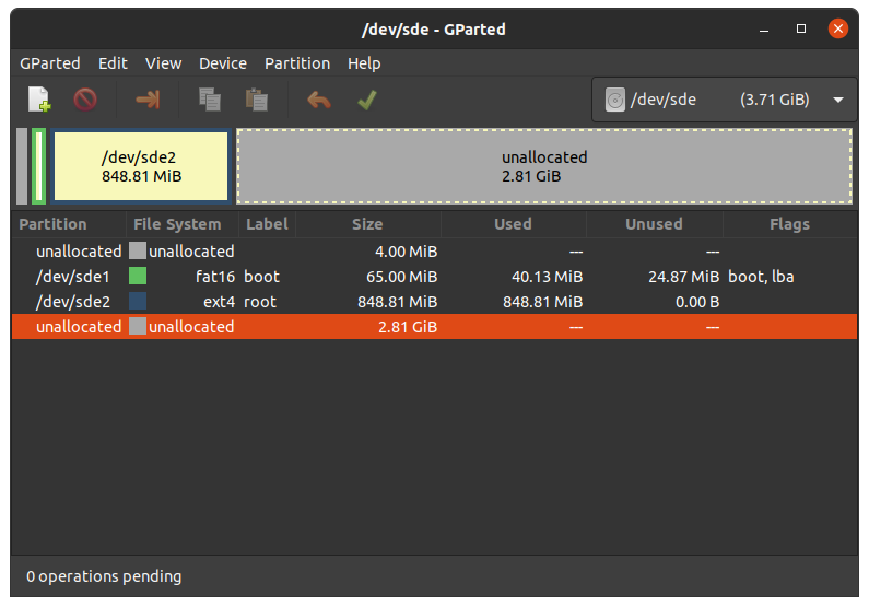
5.8.1.1. 扩展根文件系统
警告
使用resize2fs版本1.46.6及更早版本的PC系统(例如Ubuntu 22.04)无法烧写在Mickledore以及更新的yocto版本上创建的partup软件包。这个是因为resize2fs新增了默认选项而导致的兼容性问题。有关详细信息,请参阅 发布说明 。
Choose your SD card device at the drop-down menu on the top right
选择 ext4 根分区并点击调整大小:
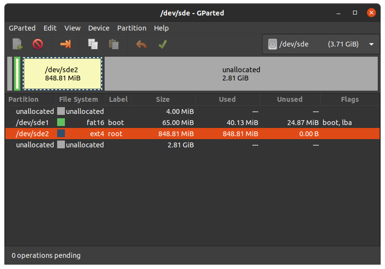
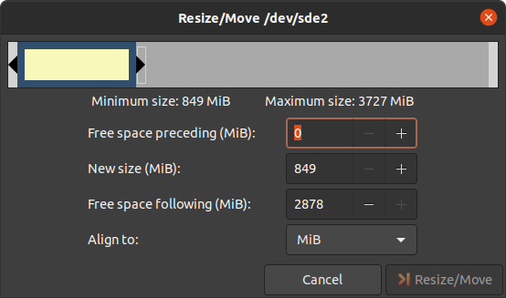
您可以根据需要拖动滑块或手动输入大小。
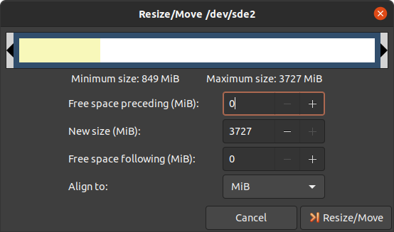
通过点击“Change Size”按钮确认您的输入。

要应用您的更改,请按绿色勾号。
现在您可以挂载根分区并将 phytec-qt6demo-image-am62lxx-libra-fpsc-1.wic 镜像复制到其中。然后再卸载它:
host:~$ sudo cp phytec-qt6demo-image-am62lxx-libra-fpsc-1.wic /mnt/ ; sync
host:~$ umount /mnt
5.8.1.2. 创建第三个分区
Choose your SD card device at the drop-down menu on the top right
选择更大的未分配区域,然后点击"New":
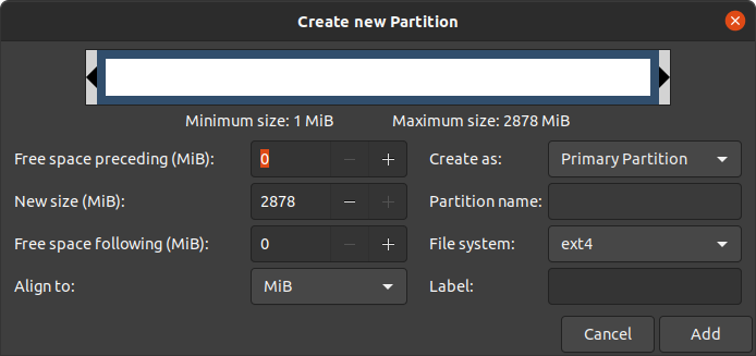
点击"Add"
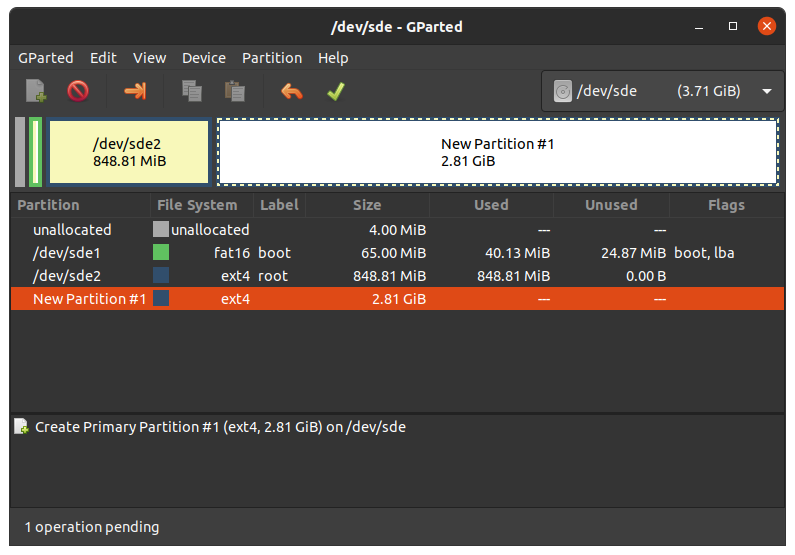
按绿色勾确认更改。
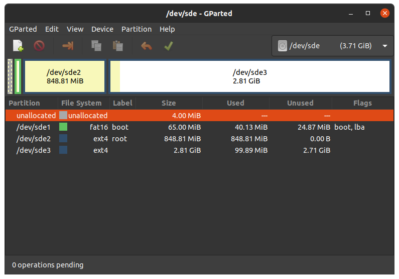
现在您可以挂载新的分区并将 phytec-qt6demo-image-am62lxx-libra-fpsc-1.wic 镜像复制到其中。然后卸载它:
host:~$ sudo mount /dev/sde3 /mnt
host:~$ sudo cp phytec-qt6demo-image-am62lxx-libra-fpsc-1.wic /mnt/ ; sync
host:~$ umount /mnt
6. 设备树 (DT)
6.1. 介绍
以下文本简要描述了设备树,关于设备树的相关文档可以在Linux kernel文档中找到(https://docs.kernel.org/devicetree/usage-model.html)。
“Open Firmware Device Tree”或简称设备树(DT)是一种用于描述硬件的数据结构和语言。更具体地说,它是一个可由操作系统读取的硬件描述,以便操作系统不需要对machine的细节进行硬编码
内核文档是学习设备树的一个非常好的资源。关于设备树数据格式的概述可以在 devicetree.org 的设备树使用页面找到。
6.2. PHYTEC AM62L BSP设备树概念
以下部分说明了PHYTEC配置基于 AM62L 的核心板设备树的一些规则。
6.2.1. 设备树结构
Module.dtsi - 文件包括所有安装在核心板上的设备,例如PMIC和RAM。
Board.dts - 包含核心板 dtsi 文件。从SoC AM62L 引出并在底板使用的设备也包含在此 dts 中。
Overlay.dtso - 根据核心板或底板上可选硬件(例如 SPI 闪存或 PEB-AV-10)的情况来启用/禁用一些功能。
在Linux内核的根目录下,我们的 AM62 平台的设备树文件可以在 arch/arm64/boot/dts/freescale/ 找到。
6.2.2. 设备树Overlay
设备树Overlay是可以在启动时合并到设备树中的设备树片段。下面是扩展板的硬件描述。对比源码中的include,overlay通过覆盖的方式来生效。overlay也可以根据实际开发板的硬件配置来设置设备树节点状态。设备树Overlay与我们Linux内核仓库中的其他设备树文件一起放在子文件夹 arch/arm64/boot/dts/freescale/ 中。
am62lxx-libra-fpsc-1.conf 可用的overlay文件有:
k3-am62l3-libra-fpsc-lvds-ac209.dtbo
可以在linux中使用以下命令来列出FIT镜像中所有的overlay配置
host:~$ dumpimage -l /boot/fitImage
或者在u-boot:
u-boot=> load mmc ${mmcdev}:1 ${loadaddr} fitImage
u-boot=> iminfo
可以在Linux或U-Boot环境下配置overlay。overlay是在引导命令调用后、内核加载之前生效。接下来的部分将更详细地解释配置方法。
6.2.2.1. 设置 ${overlays} 变量
${overlays} U-Boot 环境变量包含一个以井号#分隔的overlay文件列表,这些overlay文件将在启动过程中应用。overlays变量中的overlay列表会包含在FIT镜像中。在 $KERNEL_DEVICETREE 这个 Yocto machine 变量中设置的 overlay 文件将自动添加到FIT镜像中。
${overlays} 变量可以直接在U-Boot环境中设置,也可以作为外部 bootenv.txt 环境文件的一部分。当希望使用在U-Boot环境中手工配置的overlay变量,可以配置 env set no_bootenv 1 ,因为overlay变量可能在运行启动脚本时被覆盖。默认情况下, ${overlays} 变量来自位于启动分区的 bootenv.txt 文件。您可以在已启动的开发板上从Linux读取和写入该文件:
target:~$ cat /boot/bootenv.txt
overlays=conf-k3-am62l3-libra-rdk-fpsc-peb-eval-01.dtbo#conf-|dtbo-peb-av-10|
更改将在下次重启后生效。如果没有可用的 bootenv.txt 文件,可以直接在U-Boot环境中设置overlay变量。
u-boot=> setenv overlays conf-|dtbo-peb-av-10|
u-boot=> printenv overlays
overlays=conf-|dtbo-peb-av-10|
u-boot=> boot
如果用户定义了 ${overlays} 变量,同时存在 bootenv.txt 文件,则需要设置 ${no_bootenv} 变量:
u-boot=> setenv no_bootenv 1
u-boot=> setenv overlays conf-|dtbo-peb-av-10|
u-boot=> boot
有关环境的更多信息,请参见 U-boot External Environment subsection of the device tree overlay section。
我们使用 ${overlays} 变量来描述在运行时无法自动检测的扩展板和摄像头。如果想禁用 ${overlays} 变量中列出的overlay,可以在U-Boot的环境中将overlay变量unset,并且将 ${no_overlays} 变量设置为 1。
u-boot=> env delete overlays
u-boot=> env set no_bootenv 1
如果希望通过 bootenv.txt 文件设置除overlay之外的 U-Boot 变量并且禁用overlay,可以从 bootenv.txt 文件中删除overlay定义行,而不是设置 no_bootenv。
6.2.2.2. 不同的SoM配置
核心板会自动加载额外的overlay,以禁用核心板未贴装的组件。通过读取出厂EEPROM数据(EEPROM SoM Detection)来实现自动加载对应的overlay。
核心板型号会决定是否应用设备树overlay。要在U-Boot环境中查询是否会应用某个overlay,请运行:
u-boot=> env print fit_extensions
如果没有可用的EEPROM数据,则不加载任何设备树overlay。
要禁止启动时自动加载不同核心板的overlay,可以在bootloader环境中将 ${no_extensions} 变量设置为 1 :
u-boot=> setenv no_extensions 1
u-boot=> boot
6.2.3. U-boot外部环境
在Linux内核启动时,外部环境 bootenv.txt 文本文件将从MMC设备的boot分区或通过TFTP加载。该文件的主要目的是存储 ${overlays} 变量。这可以针对不同的machine在Yocto中预定义不同的overlay配置。文件的内容在meta-phytec中的Yocto recipe中的bootenv中定义: https://github.com/phytec/meta-phytec/tree/scarthgap/recipes-bsp/bootenv
该文件中也可以设置其他变量。这些变量将覆盖环境中现有的设置。但只有对boot命令后进行计算的变量生效,例如 ${nfsroot} 或 ${mmcargs}。在文件中更改其他变量将不会有作用。以网络启动的用法作为示例。
如果无法加载外部环境,启动过程将继续进行,并使用自带的环境变量值。
6.2.4. 在Linux环境下更改开发板上的U-boot环境变量
Libubootenv是我们镜像中包含的一个工具,用于在开发板linux上修改U-Boot环境。
使用以下命令打印U-Boot环境:
target:~$ fw_printenv
使用以下命令修改U-Boot环境:
target:~$ fw_setenv <variable> <value>
小心
Libubootenv会读取配置文件中配置的环境变量。要修改的环境变量会被插入到该文件中,默认情况下使用eMMC中存储环境变量。
如果eMMC没有被烧写过或者eMMC环境被擦除,libubootenv将无法工作。您应该修改 /etc/fw_env.config 文件,以匹配您想要使用的环境源。
7. 访问外设
To find out which boards and modules are supported by the release of PHYTEC's phyFLEX-AM62L FPSC BSP described herein, visit our BSP web page and click the corresponding BSP release in the download section. Here you can find all hardware supported in the columns "Hardware Article Number" and the correct machine name in the corresponding cell under "Machine Name".
为了最大化软件的可复用性,Linux内核提供了一个巧妙的软件架构,软件会根据不同硬件组件来分层。BSP(板级支持包)尽可能地对套件的功能进行模块化。当定制开发板或自定义核心板时,大部分软件配置可以简单的复制粘贴。与具体的开发板相关的内核代码可以在内核代码仓库中的设备树(DT)中找到,路径为 arch/arm64/boot/dts/freescale/*.dts 。
实际上,软件复用是Linux内核最重要的特性之一,尤其是在ARM架构中,它必须应对大量复杂且不同的系统级芯片(SoC)。整个开发板的硬件在设备树(DT)中描述,独立于内核镜像。硬件描述在一个单独的二进制文件中,称为设备树二进制文件(Device Tree Blob,DTB)(参见 device tree)。
请阅读PHYTEC AM62L BSP设备树概念部分,以了解我们的 AM62 BSP设备树模型。
以下部分概述了 AM62 平台上支持的硬件组件及其对应操作系统驱动程序。客户可以根据自身的需求进行更改。
7.1. AM62L 引脚复用
该 AM62L Soc包含许多外设接口。为了在保持最大功能性的同时减少封装尺寸和降低整体系统成本,许多 AM62L 引脚可以多路复用为多达八种信号功能。尽管存在许多可能的引脚多路复用组合,但由于时序限制,只有一定数量的组合被称为有效的 IO 集合。这些有效的 IO 集合经过精心挑选,以为用户提供尽可能多的应用场景。
Please refer to our Hardware Manual or the TI AM62L Reference Manual for more information about the specific pins and the muxing capabilities.
IO 集合的配置,也称为复用(muxing),是在设备树中完成的。驱动程序pinctrl-single读取设备树的节点fsl,pins,并进行引脚复用配置。
The following is an example of the pin muxing of the UART0 device in k3-am62l3-libra-rdk-fpsc.dtsi:
main_uart0_pins_default: main-uart0-default-pins {
   pinctrl-single,pins = <
      AM62LX_IOPAD(0x01b4, PIN_INPUT, 0)      /* (D13) UART0_RXD */
      AM62LX_IOPAD(0x01b8, PIN_OUTPUT, 0)     /* (C13) UART0_TXD */
   >;
   bootph-all;
};
The first argument of the macro AM62LX_IOPAD(pa, val, muxmode) is the pad offset address within the I/O controller (in this example 0x1b4, corresponding UART0_RXD). The second argument (val) specifies the pad configuration, such as input/output and pull-up/pull-down. Third argument (muxmode) selects the functional mux mode for the pad, i.e. which peripheral signal is connected to it. In this case, 0 corresponds to the default mux option for UART0.
The device tree representation for UART0 pinmuxing: https://github.com/phytec/linux-phytec-ti/tree/v6.12.35-11.01.05-phy/arch/arm64/boot/dts/ti/k3-am62l3-libra-rdk-fpsc.dts#L150
7.2. RS232
The FPSC Standard supports 3 UART units. On the Libra FPSC, TTL level signals of UART0 (the standard console) and WKUP_UART0 are routed to a FT4232H UART to USB converter expansion. This USB is brought out at USB-C connector X14. UART4 is connected to a multi-protocol transceiver for RS-232 and RS-485, available at pin header connector X27 at the RS-232 level, or at the RS-485 level. The muxing of the used transceivers is done by switch S5 on the baseboard. For more information about the correct setup please refer to the phyFLEX-AM62L FPSC/Libra FPSC Hardware Manual section UARTs. The switch S5 need to be set correctly.
以人类可读的格式显示终端的当前设置:
target:~$ stty -a
通过简单的echo和cat,可以测试基本的通信。示例:
target:~$ echo 123 > /dev/ttyS1
host:~$ cat /dev/ttyUSB2
The device tree representation for RS232: https://github.com/phytec/linux-phytec-ti/tree/v6.12.35-11.01.05-phy/arch/arm64/boot/dts/ti/k3-am62l3-libra-rdk-fpsc.dts#L327
7.3. 网络
Libra FPSC-AM62L 提供两个以太网接口。我们的核心板和底板各提供一个千兆以太网接口。
警告
The naming convention of the Ethernet interfaces in the hardware (ETH0 and ETH1) do not align with the network interfaces (end0 and end1) in Linux. So, be aware of these differences:
所有接口都提供一个标准的Linux网络端口,可以使用BSD套接字接口进行编程。整个网络配置由systemd-networkd守护进程管理。相关的配置文件可以在开发板的 /lib/systemd/network/ 目录中找到,以及在BSP中的 meta-ampliphy/recipes-core/systemd/systemd-conf 目录中。
IP addresses can be configured within *.network files. The interfaces are configured to static IP as default. The default IP address and netmask for end0 is:
end0: 192.168.3.11/24
To configure end0 to dynamic IP over DHCP, go to
/lib/systemd/network/\*-end0.network
and delete the line:
Address=192.168.3.11/24
The DT Ethernet setup might be split into two files depending on your hardware configuration: the module DT and the board-specific DT. The device tree set up for the ethernet where the PHY is populated on the SoM can be found here: https://github.com/phytec/linux-phytec-ti/tree/v6.12.35-11.01.05-phy/arch/arm64/boot/dts/ti/k3-am62l-phycore-fpsc.dtsi#L148 `.
The device tree set up for EQOS Ethernet IP core where the PHY is populated on the Libra FPSC can be found here: https://github.com/phytec/linux-phytec-ti/tree/v6.12.35-11.01.05-phy/arch/arm64/boot/dts/ti/k3-am62l3-libra-rdk-fpsc.dts#L213.
7.3.1. 网络配置
7.3.1.1. U-boot网络环境
要在bootloader中查找以太网设置:
u-boot=> printenv ipaddr serverip netmask
在将主机设置为IP 192.168.3.10和子网掩码255.255.255.0的情况下,开发板应该返回:
u-boot=> printenv ipaddr serverip netmask
ipaddr=192.168.3.11
serverip=192.168.3.10
netmask=255.225.255.0
如果您需要进行任何更改:
u-boot=> setenv <parameter> <value>
<parameter> 应该是 ipaddr、netmask、gatewayip 或 serverip 中的一个。<value> 将是所选参数的设定值。
您所做的更改目前是临时的。要保存这些更改:
u-boot=> saveenv
在这里,您也可以将IP地址更改为DHCP,而不是使用静态IP地址。
配置:
u-boot=> setenv ip dhcp
设置 TFTP 和 NFS 的路径。修改可以如下所示:
u-boot=> setenv nfsroot /home/user/nfssrc
请注意,这些修改只会影响bootloader的设置。
小技巧
像nfsroot和netargs这样的变量可以被U-boot外部环境重新赋值。对于网络启动,外部环境将通过tftp加载。例如,要在 bootenv.txt 文件中设置nfsroot变量,请在tftproot目录修改:
nfsroot=/home/user/nfssrc
无需在开发板上存储这些信息。请注意,U-boot外部环境对于像 ipaddr 或 serveraddr 这样的变量不起作用,因为它们在加载外部环境之前已经被设置完成。
7.3.1.1.1. Multiple network interfaces in U-Boot
Some boards may have support for multiple network interfaces in U-Boot. U-Boot lists all supported network interfaces during startup. This generic example illustrates support for multiple network interfaces:
Net:
eth0: ethernet@10000000, eth1: ethernet@10010000
There are three environment variables that will contribute to the selection of the ethernet interface for example when loading a file over tftp.
ethrotateDetermines if other interfaces will be probed if the first one fails. Valid values are yes/no. Default is yes if unset.
ethactSets the current active ethernet interface. This interface will be used (first). It is usually unset at boot, but will be set automatically by U-Boot to the last used interface as soon as ethernet is used for the first time. U-Boot will overwrite existing values. Only one ethernet interface can be set, lists are not allowed.
ethprimeThis will determine the preferred ethernet interface if ethact is unset. Otherwise this will be ignored. Only one ethernet interface can be set, lists are not allowed.
备注
The variables ipaddr, serverip and netmask are global and not specific to a
certain ethernet interface, so they might need to be adapted to the ethernet
interface in use.
7.3.1.1.2. Secondary Ethernet Interface Configuration in U-Boot
By default, U-Boot utilizes the Ethernet PHY located on the module. To use the network connection provided by the PHY on the carrier board, configuration changes are required.
To enable the secondary Ethernet interface in U-Boot, the active Ethernet connection must be adjusted. The IP address configuration in U-Boot may also need modification.
Configure the development host with IP address 192.168.4.10 and netmask 255.255.255.0. The target device must then be configured as follows:
u-boot=> setenv ethact eth1
u-boot=> setenv ipaddr 192.168.4.11
7.3.1.2. 内核网络环境
Find the ethernet settings for end0 in the target kernel:
target:~$ ip -statistics address show end0
2: end0: <NO-CARRIER,BROADCAST,MULTICAST,UP> mtu 1500 qdisc mq state UP group default qlen 1000
    link/ether 50:2d:f4:19:d6:33 brd ff:ff:ff:ff:ff:ff
    RX:  bytes packets errors dropped  missed   mcast
             0       0      0       0       0       0
    TX:  bytes packets errors dropped carrier collsns
             0       0      0       0       0       0
Temporary adaption of the end0 configuration:
target:~$ ip address add 192.168.3.11/24 dev end0
7.4. SD card
The AM62L supports a slot for Secure Digital cards to be used as general-purpose block devices. These devices can be used in the same way as any other block device.
警告
这些设备是热插拔的。然而,您必须确保在设备仍然挂载时不要拔掉它。这可能会导致数据丢失!
After inserting an SD card, the kernel will generate new device nodes in /dev. The full device can be reached via its /dev/mmcblk1 device node. SD card partitions will show up as:
/dev/mmcblk1p<Y>
<Y> 作为分区编号,从1开始计数,直到该设备的最大分区数量。分区可以使用任何类型的文件系统进行格式化,并且可以以标准方式进行处理,例如,可以使用mount 和 umount 命令进行分区挂载和卸载。
小技巧
这些分区设备节点要求SD卡包含有效的分区表(类似于“硬盘”)。如果没有分区表,则整个设备作为一个文件系统使用(类似于“软盘”)。在这种情况下,必须使用 /dev/mmcblk1 进行格式化和挂载。卡始终以可写方式挂载。
DT configuration for the MMC (SD card slot) interface can be found here: https://github.com/phytec/linux-phytec-ti/tree/v6.12.35-11.01.05-phy/arch/arm64/boot/dts/ti/k3-am62l-phycore-fpsc.dtsi#L272 and https://github.com/phytec/linux-phytec-ti/tree/v6.12.35-11.01.05-phy/arch/arm64/boot/dts/ti/k3-am62l3-libra-rdk-fpsc.dts#L355
DT configuration for the e.MMC interface can be found here: https://github.com/phytec/linux-phytec-ti/tree/v6.12.35-11.01.05-phy/arch/arm64/boot/dts/ti/k3-am62l-phycore-fpsc.dtsi#L263
7.5. e.MMC Devices
PHYTEC modules like phyFLEX-AM62L FPSC are populated with an e.MMC memory chip as the main storage. e.MMC devices contain raw Multi-Level Cells (MLC) or Triple-Level Cells (TLC) combined with a memory controller that handles ECC and wear leveling. They are connected via an SD/MMC interface to the AM62L and are represented as block devices in the Linux kernel like SD cards, flash drives, or hard disks.
The electric and protocol specifications are provided by JEDEC (https://www.jedec.org/standards-documents/technology-focus-areas/flash-memory-ssds-ufs-emmc/e-mmc). The e.MMC manufacturer's datasheet is relatively short and meant to be read together with the supported version of the JEDEC e.MMC standard.
PHYTEC currently utilizes the e.MMC chips with JEDEC Version 5.0 and 5.1
7.5.1. 扩展CSD寄存器
e.MMC devices have an extensive amount of extra information and settings that are available via the Extended CSD registers. For a detailed list of the registers, see manufacturer datasheets and the JEDEC standard.
在Linux用户空间中,您可以查询寄存器:
target:~$ mmc extcsd read /dev/mmcblk0
你将会看到:
=============================================
   Extended CSD rev 1.7 (MMC 5.0)
=============================================

 Card Supported Command sets [S_CMD_SET: 0x01]
 [...]
7.5.2. 使能后台操作 (BKOPS)
In contrast to raw NAND Flash, an e.MMC device contains a Flash Transfer Layer (FTL) that handles the wear leveling, block management, and ECC of the raw MLC or TLC. This requires some maintenance tasks (for example erasing unused blocks) that are performed regularly. These tasks are called Background Operations (BKOPS).
默认情况下(取决于芯片),后台操作可能会定期执行,也可能不会,他影响读写的最大延迟时间。
The JEDEC Standard has specified a method since version v4.41 that the host can issue BKOPS manually. See the JEDEC Standard chapter Background Operations and the description of registers BKOPS_EN (Reg: 163) and BKOPS_START (Reg: 164) in the e.MMC datasheet for more details.
寄存器 BKOPS_EN(寄存器:163)的位 MANUAL_EN(位 0)的含义:
值 0:主机不支持手动触发 BKOPS。设备写入性能会受到影响。
值1:主机支持手动触发BKOPS。当主机不进行设备读写时,它会不时触发BKOPS。
The mechanism to issue background operations has been implemented in the Linux kernel since v3.7. You only have to enable BKOPS_EN on the e.MMC device (see below for details).
JEDEC标准v5.1引入了一种新的自动BKOPS功能。它使主机能够定期触发后台操作,因为设备在空闲时会自动启动BKOPS(请参见寄存器BKOPS_EN(寄存器:163)中位AUTO_EN的描述)。
要检查 BKOPS_EN 是否已设置,请执行:
target:~$ mmc extcsd read /dev/mmcblk0 | grep BKOPS_EN
输出将会是,例如:
Enable background operations handshake [BKOPS_EN]: 0x01
#OR
Enable background operations handshake [BKOPS_EN]: 0x00
值0x00表示BKOPS_EN被禁用,设备的写入性能受到影响。值0x01表示BKOPS_EN被启用,主机将不时发起后台操作。
通过以下命令使能BKOPS_EN:
target:~$ target:~$ mmc --help

[...]
mmc bkops_en <auto|manual> <device>
    Enable the eMMC BKOPS feature on <device>.
    The auto (AUTO_EN) setting is only supported on eMMC 5.0 or newer.
    Setting auto won't have any effect if manual is set.
    NOTE!  Setting manual (MANUAL_EN) is one-time programmable (unreversible) change.
要设置BKOPS_EN位,请执行:
target:~$ mmc bkops_en manual /dev/mmcblk0
为了确保新设置生效并且内核能够自动触发BKOPS,请先关闭系统:
target:~$ poweroff
小技巧
BKOPS_EN位是一次性可编程的,无法恢复。
7.5.3. 可靠写入
有两种不同的可靠写入选项:
Reliable Write option for a whole e.MMC device/partition.
单次写的可靠写入方式。
小技巧
Do not confuse e.MMC partitions with partitions of a DOS, MBR, or GPT partition table (see the previous section).
The first Reliable Write option is mostly already enabled on the e.MMCs mounted on the phyFLEX-AM62L FPSC SoMs. To check this on the running target:
target:~$ mmc extcsd read /dev/mmcblk0 | grep -A 5 WR_REL_SET
Write reliability setting register [WR_REL_SET]: 0x1f
 user area: the device protects existing data if a power failure occurs during a write o
peration
 partition 1: the device protects existing data if a power failure occurs during a write
 operation
 partition 2: the device protects existing data if a power failure occurs during a write
 operation
 partition 3: the device protects existing data if a power failure occurs during a write
 operation
 partition 4: the device protects existing data if a power failure occurs during a write
 operation
--
 Device supports writing EXT_CSD_WR_REL_SET
 Device supports the enhanced def. of reliable write
如果默认没有启用,可以使用mmc工具启用它:
target:~$ mmc --help

[...]
mmc write_reliability set <-y|-n|-c> <partition> <device>
    Enable write reliability per partition for the <device>.
    Dry-run only unless -y or -c is passed.
    Use -c if more partitioning settings are still to come.
    NOTE!  This is a one-time programmable (unreversible) change.
第二个可靠写入方式是命令CMD23中的配置位Reliable Write Request parameter(可靠写入请求参数)(位31)。自内核版本v3.0起,文件系统(例如ext4的日志)和用户空间应用程序(如fdisk的分区表)会通过内核使用该可靠写功能。在Linux内核源代码中,它通过标志REQ_META进行处理。
结论:使用挂载选项 data=journal 的 ext4 文件系统在断电情况下是安全的。文件系统检查可以在断电后恢复文件系统,但在断电前刚写入的数据可能会丢失。在各种情况下,都可以恢复文件系统的正常状态。为了确保应用程序文件的正常保存,应用程序中应使用系统函数 fdatasync 或 fsync。
7.5.4. 调整 ext4 根文件系统的大小
When flashing the SD card image to e.MMC the ext4 root partition is not extended to the end of the e.MMC. parted can be used to expand the root partition. The example works for any block device such as e.MMC, SD card, or hard disk.
获取当前设备大小:
target:~$ parted /dev/mmcblk0 print
输出如下:
Model: MMC Q2J55L (sd/mmc)
Disk /dev/mmcblk0: 7617MB
Sect[ 1799.850385]  mmcblk0: p1 p2
or size (logical/physical): 512B/512B
Partition Table: msdos
Disk Flags:

Number  Start   End     Size    Type     File system  Flags
 1      4194kB  72.4MB  68.2MB  primary  fat16        boot, lba
 2      72.4MB  537MB   465MB   primary  ext4
使用parted将文件系统分区调整为设备的最大大小:
target:~$ parted /dev/mmcblk0 resizepart 2 100%
Information: You may need to update /etc/fstab.

target:~$ parted /dev/mmcblk0 print
Model: MMC Q2J55L (sd/mmc)
Disk /dev/mmcblk0: 7617MB
Sector size (logical/physical): 512[ 1974.191657]  mmcblk0: p1 p2
B/512B
Partition Table: msdos
Disk Flags:

Number  Start   End     Size    Type     File system  Flags
 1      4194kB  72.4MB  68.2MB  primary  fat16        boot, lba
 2      72.4MB  7617MB  7545MB  primary  ext4
将文件系统调整为新的分区大小:
target:~$ resize2fs /dev/mmcblk0p2
resize2fs 1.46.1 (9-Feb-2021)
Filesystem at /dev/mmcblk0p2 is mounted on /; on-line resizing required
[ 131.609512] EXT4-fs (mmcblk0p2): resizing filesystem
from 454136 to 7367680 blocks
old_desc_blocks = 4, new_desc_blocks = 57
[ 131.970278] EXT4-fs (mmcblk0p2): resized filesystem to 7367680
The filesystem on /dev/mmcblk0p2 is now 7367680 (1k) blocks long
Increasing the filesystem size can be done while it is mounted. But you can also boot the board from an SD card and then resize the file system on the e.MMC partition while it is not mounted.
7.5.5. 启用伪SLC模式
e.MMC devices use MLC or TLC (https://en.wikipedia.org/wiki/Multi-level_cell) to store the data. Compared with SLC used in NAND Flash, MLC or TLC have lower reliability and a higher error rate at lower costs.
如果您更喜欢可靠性而不是存储容量,可以启用伪SLC模式或SLC模式。这个方法采用了增强属性,该属性在JEDEC标准中有所描述,可以对设备的一个连续区域设置。JEDEC标准并未规定增强属性的实现细节和保证,这由芯片制造商自行决定。对于美光(Micron)芯片,增强属性提高了可靠性,但也将容量减半。
警告
在设备上启用增强属性时,所有数据将被丢失。
以下步骤展示了如何启用增强属性。
First obtain the current size of the e.MMC device with:
target:~$ parted -m /dev/mmcblk0 unit B print
你将收到:
BYT;
/dev/mmcblk0:63652757504B:sd/mmc:512:512:unknown:MMC S0J58X:;
如您所见,该设备的容量为 63652757504 字节 = 60704 MiB。
要获取启用伪SLC模式后的设备的大小,请使用:
target:~$ mmc extcsd read /dev/mmcblk0 | grep ENH_SIZE_MULT -A 1
例如:
Max Enhanced Area Size [MAX_ENH_SIZE_MULT]: 0x000764
i.e. 3719168 KiB
--
Enhanced User Data Area Size [ENH_SIZE_MULT]: 0x000000
i.e. 0 KiB
这里的最大大小是3719168 KiB = 3632 MiB。
现在,您可以通过输入以下命令为整个设备设置增强属性,例如 3719168 KiB:
target:~$ mmc enh_area set -y 0 3719168 /dev/mmcblk0
你将获得:
Done setting ENH_USR area on /dev/mmcblk0
setting OTP PARTITION_SETTING_COMPLETED!
Setting OTP PARTITION_SETTING_COMPLETED on /dev/mmcblk0 SUCCESS
Device power cycle needed for settings to take effect.
Confirm that PARTITION_SETTING_COMPLETED bit is set using 'extcsd read' after power cycle
为了确保新设置已生效,请关闭系统:
target:~$ poweroff并进行上下电。建议您现在确认设置是否正确。
首先,检查ENH_SIZE_MULT的值,它必须是3719168 KiB:
target:~$ mmc extcsd read /dev/mmcblk0 | grep ENH_SIZE_MULT -A 1
您应该看到:
Max Enhanced Area Size [MAX_ENH_SIZE_MULT]: 0x000764
i.e. 3719168 KiB
--
Enhanced User Data Area Size [ENH_SIZE_MULT]: 0x000764
i.e. 3719168 KiB
最后,检查设备的大小:
target:~$ parted -m /dev/mmcblk0 unit B print
BYT;
/dev/mmcblk0:31742492672B:sd/mmc:512:512:unknown:MMC S0J58X:;
7.5.6. 擦除设备
It is possible to erase the e.MMC device directly rather than overwriting it with zeros. The e.MMC block management algorithm will erase the underlying MLC or TLC or mark these blocks as discard. The data on the device is lost and will be read back as zeros.
After booting from SD card execute:
target:~$ blkdiscard -f --secure /dev/mmcblk0
选项 --secure 确保命令在 eMMC 设备擦除所有块之前会等待。-f (强制) 选项强制擦写,当 eMMC 设备包含有效数据分区时需要使用-f选项。
小技巧
target:~$ dd if=/dev/zero of=/dev/mmcblk0 conv=fsync
该命令也会擦除设备上的所有信息,但这个命令不利于设备的磨损均衡,并且需要花费更长的时间!
7.5.7. e.MMC Boot Partitions
An e.MMC device contains four different hardware partitions: user, boot1, boot2, and rpmb.
The user partition is called the User Data Area in the JEDEC standard and is the main storage partition. The partitions boot1 and boot2 can be used to host the bootloader and are more reliable. Which partition the AM62L uses to load the bootloader is controlled by the boot configuration of the e.MMC device. The partition rpmb is a small partition and can only be accessed via a trusted mechanism.
此外,User分区可以分为四个自定义的一般用途分区。对此功能的解释不在本文件涵盖的范围。有关更多信息,请参阅JEDEC标准第7.2章分区管理。
小技巧
Do not confuse e.MMC partitions with partitions of a DOS, MBR, or GPT partition table.
The current PHYTEC BSP does not use the extra partitioning feature of e.MMC devices. The U-Boot is flashed at the beginning of the user partition. The U-Boot environment is placed at a fixed location after the U-Boot. An MBR partition table is used to create two partitions, a FAT32 boot, and ext4 rootfs partition. They are located right after the U-Boot and the U-Boot environment. The FAT32 boot partition contains the kernel and device tree.
With e.MMC flash storage it is possible to use the dedicated boot partitions for redundantly storing the bootloader. The Bootloader environment still resides in the user area before the first partition. The user area also still contains the bootloader which the image first shipped during its initialization process. Below is an example, to flash the bootloader to one of the two boot partitions and switch the boot device via userspace commands.
7.5.7.1. 通过用户空间命令
在主机上运行:
host:~$ scp <bootloader> root@192.168.3.11:/tmp/
The partitions boot1 and boot2 are read-only by default. To write to them from
user space, you have to disable force_ro in the sysfs.
To manually write the bootloader to the e.MMC boot partitions, first disable the write protection:
target:~$ echo 0 > /sys/block/mmcblk0boot0/force_ro
target:~$ echo 0 > /sys/block/mmcblk0boot1/force_ro
Write the bootloader to the e.MMC boot partitions:
target:~$ dd if=/tmp/<bootloader> of=/dev/mmcblk0boot0
target:~$ dd if=/tmp/<bootloader> of=/dev/mmcblk0boot1
下表是 AM62L SoC的偏移量:
SoC |
User分区偏移量 |
Boot分区偏移量 |
e.MMC Device |
|---|---|---|---|
AM62L |
32 kiB |
0 kiB |
/dev/mmcblk0 |
After that set the boot partition from user space using the mmc tool:
(对于 'boot0') :
target:~$ mmc bootpart enable 1 0 /dev/mmcblk0
(对于'boot1'):
target:~$ mmc bootpart enable 2 0 /dev/mmcblk0
To disable booting from the e.MMC boot partitions simply enter the following command:
target:~$ mmc bootpart enable 0 0 /dev/mmcblk0
To explicitly enable booting from the e.MMC user area, run:
target:~$ mmc bootpart enable 7 0 /dev/mmcblk0
7.5.7.2. Automatic failover
The ROM loader implements an automatic failover mechanism for e.MMC boot partitions. If booting
from the primary partition fails, the system automatically attempts to boot from the secondary
partition. This failover is indicated by a change in the boot message from
Boot Stage: Primary boot to Boot Stage: Secondary boot.
This functionality is limited to boot0 and boot1 partitions and does not apply to the user area.
7.6. SPI主设备
The AM62L controller has MCSPI and an OSPI controllers included. The MCSPI controller supports four SPI channels with each up to 4 devices. The OSPI controllers supports Single/Dual/Quad/Octal mode data transfer (1/2/4/8 bidirectional data lines).
7.6.1. SPI NOR 烧写
Libra FPSC is equipped with a QSPI NOR Flash which connects to the AM62L's OSPI interface.
From Linux userspace, the NOR Flash partitions are accessible via /dev/mtd<N> devices where <N> is the MTD device number associated with the NOR flash partition to access. To find the correct MTD device number for a partition, run on the target:
root@am62lxx-libra-fpsc-1:~$ mtdinfo --all
Count of MTD devices:           5
Present MTD devices:            mtd0, mtd1, mtd2, mtd3, mtd4
Sysfs interface supported:      yes

mtd0
Name:                           ospi.tiboot3
Type:                           nor
Eraseblock size:                131072 bytes, 128.0 KiB
Amount of eraseblocks:          4 (524288 bytes, 512.0 KiB)
Minimum input/output unit size: 1 byte
Sub-page size:                  1 byte
Character device major/minor:   90:0
Bad blocks are allowed:         false
Device is writable:             true

mtd1
Name:                           ospi.tispl
Type:                           nor
Eraseblock size:                131072 bytes, 128.0 KiB
Amount of eraseblocks:          16 (2097152 bytes, 2.0 MiB)
Minimum input/output unit size: 1 byte
Sub-page size:                  1 byte
Character device major/minor:   90:2
Bad blocks are allowed:         false
Device is writable:             true

mtd2
Name:                           ospi.u-boot
Type:                           nor
Eraseblock size:                131072 bytes, 128.0 KiB
Amount of eraseblocks:          32 (4194304 bytes, 4.0 MiB)
Minimum input/output unit size: 1 byte
Sub-page size:                  1 byte
Character device major/minor:   90:4
Bad blocks are allowed:         false
Device is writable:             true

mtd3
Name:                           ospi.env
Type:                           nor
Eraseblock size:                131072 bytes, 128.0 KiB
Amount of eraseblocks:          2 (262144 bytes, 256.0 KiB)
Minimum input/output unit size: 1 byte
Sub-page size:                  1 byte
Character device major/minor:   90:6
Bad blocks are allowed:         false
Device is writable:             true

mtd4
Name:                           ospi.env.backup
Type:                           nor
Eraseblock size:                131072 bytes, 128.0 KiB
Amount of eraseblocks:          2 (262144 bytes, 256.0 KiB)
Minimum input/output unit size: 1 byte
Sub-page size:                  1 byte
Character device major/minor:   90:8
Bad blocks are allowed:         false
Device is writable:             true
它列出了所有MTD设备及其对应的分区名称。闪存节点在模块DTS中的SPI主节点内定义。SPI节点包含连接到此SPI总线的所有设备,在这种情况下只有SPI NOR Flash。
设备树中SPI主节点的定义可以在这里找到:
7.7. GPIOs
The Libra FPSC has a set of pins especially dedicated to user I/Os. Those pins are connected directly to AM62L pins and are muxed as GPIOs. They are directly usable in Linux userspace. The processor has organized its GPIOs into nine banks of 16 GPIOs each (up to 144 GPIOs). However, not all GPIOs are pinned out on the Libra FPSC board.
In Linux, the internal GPIO module is exposed as a single GPIO controller, represented by gpiochip0. This controller provides access to all available GPIOs on the device. On the Libra FPSC, this corresponds to 126 GPIO lines in total.
从用户空间访问GPIO将使用libgpiod。它提供了一个库和工具,用于与Linux GPIO字符设备进行交互。以下是一些工具的用法示例:
检测芯片上的gpiochips:
target:~$ gpiodetect
gpiochip0 [600000.gpio] (126 lines)
GPIO expander
Beside the GPIOs of the AM62L SoC, the Libra FPSC has a GPIO expander, which adds more GPIOs to the system.
gpiochip2 [4-0020] (16 lines)DT configuration for the GPIO expander can be found here:
显示关于gpiochips的详细信息,包括它们的名称、consumer、方向、活动状态和附加flag:
target:~$ gpioinfo -c gpiochip0
读取GPIO的值(例如从gpiochip0的GPIO 20):
target:~$ gpioget -c gpiochip0 20
将gpiochip0上的GPIO 20的值设置为0并退出工具:
target:~$ gpioset -z -c gpiochip0 20=0
gpioset的帮助文本显示了可能的选项:
target:~$ gpioset --help
Usage: gpioset [OPTIONS] <line=value>...

Set values of GPIO lines.

Lines are specified by name, or optionally by offset if the chip option
is provided.
Values may be '1' or '0', or equivalently 'active'/'inactive' or 'on'/'off'.

The line output state is maintained until the process exits, but after that
is not guaranteed.

Options:
      --banner            display a banner on successful startup
  -b, --bias <bias>       specify the line bias
                  Possible values: 'pull-down', 'pull-up', 'disabled'.
                  (default is to leave bias unchanged)
      --by-name           treat lines as names even if they would parse as an offset
  -c, --chip <chip>       restrict scope to a particular chip
  -C, --consumer <name>   consumer name applied to requested lines (default is 'gpioset')
  -d, --drive <drive>     specify the line drive mode
                  Possible values: 'push-pull', 'open-drain', 'open-source'.
                  (default is 'push-pull')
  -h, --help              display this help and exit
  -l, --active-low        treat the line as active low
  -p, --hold-period <period>
                  the minimum time period to hold lines at the requested values
  -s, --strict            abort if requested line names are not unique
  -t, --toggle <period>[,period]...
                  toggle the line(s) after the specified period(s)
                  If the last period is non-zero then the sequence repeats.
      --unquoted  don't quote line names
  -v, --version           output version information and exit
  -z, --daemonize set values then detach from the controlling terminal

Chips:
    A GPIO chip may be identified by number, name, or path.
    e.g. '0', 'gpiochip0', and '/dev/gpiochip0' all refer to the same chip.

Periods:
    Periods are taken as milliseconds unless units are specified. e.g. 10us.
    Supported units are 's', 'ms', and 'us'.

*Note*
    The state of a GPIO line controlled over the character device reverts to default
    when the last process referencing the file descriptor representing the device file exits.
    This means that it's wrong to run gpioset, have it exit and expect the line to continue
    being driven high or low. It may happen if given pin is floating but it must be interpreted
    as undefined behavior.
警告
某些GPIO用于特殊功能。在使用某个GPIO之前,请参考您板子的原理图或硬件手册,以确保该IO未被其他功能占用。
7.7.1. 通过sysfs访问GPIO
警告
通过sysfs访问GPIO已经过时了,我们建议使用libgpiod。
默认情况下不再支持通过sysfs访问GPIO。只有手动在内核配置中启用 CONFIG_GPIO_SYSFS 后才能支持。要在menuconfig中使 CONFIG_GPIO_SYSFS 可见,必须首先启用选项 CONFIG_EXPERT 。
You can also add this option for example to the defconfig you use in
arch/arm64/configs/ in the linux kernel sources. For our TI based releases,
this could be for example phytec_ti_defconfig:
..
CONFIG_EXPERT=y
CONFIG_GPIO_SYSFS=y
..
您也可以创建一个新的config片段。有关详细信息,请参阅我们的 Yocto Reference Manual。
7.8. ADC
The PHYTEC phyFLEX-AM62L FPSC includes general purpose Analog-to-Digital Converters (ADC) which can be used for interfacing analog sensors.
通过sysfs可以读取ADC值:
target:~$ cat /sys/bus/iio/devices/iio:deviceX/in_voltageY_raw
On Libra FPSC the ADC lines are accessible on X73 expansion connector:
ADC输入 |
X73 pin |
|---|---|
ADC_IN0 |
3 |
ADC_IN1 |
5 |
ADC_IN2 |
7 |
ADC_IN3 |
9 |
ADC_IN4 |
4 |
ADC_IN5 |
6 |
ADC_IN6 |
8 |
ADC_IN7 |
10 |
备注
On AM62L, only ADC_IN0 to ADC_IN3 are available for use. ADC_IN4 to ADC_IN7 are not connected internally. This limitation also applies to the current/voltage sensing functionality.
Additionally, there is a current and voltage sensing circuitry available on Libra FPSC. It is capable of measuring the input current consumption and supply voltage of the phyFLEX-AM62L FPSC SoM, as well as the Libra FPSC carrier board's 1.8V, 3.3V and 5V power rails.
The current-sensing circuitry uses four INA241A4QDDFRQ1 current-sense amplifiers (gain: 100 V/V), each paired with a 4 mΩ shunt resistor. Their outputs feed the ADC input channels (Vref = 1.8 V) through a 1:3 voltage divider. With this configuration, the resulting current resolution is 3.295898 mA/LSB.
The voltage-sensing circuitry uses simple 1:3.46 voltage dividers connected to the ADC input channels (Vref = 1.8 V). This yields a voltage resolution of 1.520508 mV/LSB.
Channel Function |
ADC Input |
|---|---|
SoM current sensing |
ADC_IN0 |
SoM voltage sensing |
ADC_IN1 |
Carrier board 5V rail current sensing |
ADC_IN2 |
Carrier board 5V rail voltage sensing |
ADC_IN3 |
Carrier board 3.3V rail current sensing |
ADC_IN4 |
Carrier board 3.3V rail voltage sensing |
ADC_IN5 |
Carrier board 1.8V rail current sensing |
ADC_IN6 |
Carrier board 1.8V rail voltage sensing |
ADC_IN7 |
Current scaling factor is available as a sysfs parameter
/sys/bus/iio/devices/iio:device1/in_current0_scale.
The phyFLEX-AM62L FPSC SoM consumption can thus be measured with this simple script:
#!/bin/sh
RAW=$(cat /sys/bus/iio/devices/iio:device1/in_current0_raw)
SCALE=$(cat /sys/bus/iio/devices/iio:device1/in_current0_scale)
CURRENT=$(echo "$RAW * $SCALE" | bc -l)
printf "Current: %.3f mA\n" "$CURRENT"
备注
Current scaling factor calculation depends on CONFIG_IIO_RESCALE=y kernel configuration.
In our BSP we also enable config option CONFIG_SENSORS_IIO_HWMON=y which provides
hwmon interface to conveniently measure phyFLEX-AM62L FPSC SoM consumption directly via the sysfs
parameter:
root@|yocto-machinename|:~$ cat /sys/class/hwmon/hwmon1/curr1_input
415
In the example output provided above, the current consumption measured was 415 mA @ 5V.
7.9. LED灯
如果有任何LED灯连接到GPIO管脚,您可以通过特定的LED驱动程序接口访问它们,而不是使用通用的GPIO接口(请参见GPIO部分)。您将通过 /sys/class/leds/ 而不是 /sys/class/gpio/ 来访问它们。LED的最大亮度可以从 max_brightness 文件中读取。brightness文件将设置LED的亮度(取值范围从0到max_brightness)。大多数LED硬件上不支持调整亮度,所以在所有非零亮度下都会点亮。
下面是一个简单的例子。
要获取所有可用的LED,请输入:
target:~$ ls /sys/class/leds
led-1@  led-2@  led-3@  mmc1::@  mmc2::@
The Libra FPSC provides the following LED indicators: led-1, led-2 and led-3.
打开LED灯:
target:~$ echo 255 > /sys/class/leds/led-1/brightness
关闭LED:
target:~$ echo 0 > /sys/class/leds/led-1/brightness
Device tree configuration for the User I/O configuration can be found here: https://github.com/phytec/linux-phytec-ti/tree/v6.12.35-11.01.05-phy/arch/arm64/boot/dts/ti/k3-am62l3-libra-rdk-fpsc.dts#L251
7.10. I²C总线
该 AM62L 包含多个多主支持快速模式的 I²C模块。PHYTEC板提供了许多不同的I²C设备,这些设备连接到 AM62L 的I²C模块。 本节描述了我们 Libra FPSC 中集成的一些I²C设备的基本设备使用及其设备树(DT)表示。
i2c的设备树节点包含一些设置,例如时钟频率,用于设置总线频率,以及引脚控制设置,包括scl-gpios和sda-gpios,这些是用于总线恢复的备用引脚配置。
General I²C bus configuration from SoM (e.g. k3-am62l-phyflex-fpsc.dtsi): https://github.com/phytec/linux-phytec-ti/tree/v6.12.35-11.01.05-phy/arch/arm64/boot/dts/ti/k3-am62l-phycore-fpsc.dtsi#L172
General I²C bus configuration from carrierboard (e.g. k3-am62l3-libra-rdk-fpsc.dts) https://github.com/phytec/linux-phytec-ti/tree/v6.12.35-11.01.05-phy/arch/arm64/boot/dts/ti/k3-am62l3-libra-rdk-fpsc.dts#L233
7.11. EEPROM
The system features two I2C EEPROM devices distributed across the SoM and carrier board:
On the phyFLEX-AM62L FPSC SoM:
Board Detection EEPROM
Bus: I2C-1
Address: 0x50
Purpose: Factory configuration for board identification
Device Tree Reference for SoM EEPROMs: https://github.com/phytec/linux-phytec-ti/tree/v6.12.35-11.01.05-phy/arch/arm64/boot/dts/ti/k3-am62l-phycore-fpsc.dtsi#L249
And on the Libra FPSC carrier board:
Board Detection EEPROM
Bus: I2C-2
Address: 0x51
Purpose: Reserved for carrier board identification
Device Tree Reference for Carrier Board: https://github.com/phytec/linux-phytec-ti/tree/v6.12.35-11.01.05-phy/arch/arm64/boot/dts/ti/k3-am62l3-libra-rdk-fpsc.dts#L238
7.11.1. I2C EEPROM access
警告
The first 1024 (0x400) bytes of the EEPROM area (bus: I2C-1 addr: 0x50) should not be erased or overwritten. As this will influence the behavior of the bootloader. The board might not boot correctly anymore.
7.11.1.1. EEPROM reading and writing in U-Boot
In U-Boot the i2c command can be used for EEPROM read and write operations.
First set the correct I2C bus, where the EEPROM is connected. <bus-no> is the I2C bus number of the EEPROM.
u-boot=> i2c dev <bus-no>
To read and print the first 32 bytes from EEPROM execute. <addr> is the I2C address of the EEPROM.
u-boot=> i2c md <addr> 0x00 0x20
To read the first 32 bytes from EEPROM into memory (loadaddr) execute:
u-boot=> i2c read <addr> 0x00 0x20 $loadaddr
To write 0xff to the 32 bytes at offset 0x100 execute:
u-boot=> i2c mw <addr> 0x100 0xff 0x20
To write 32 bytes to offset 0x100 to EEPROM from memory (loadaddr) execute:
u-boot=> i2c write $loadaddr <addr> 0x100 0x20
7.11.1.2. EEPROM reading and writing in Linux
Reading and writing can also be done via sysfs in Linux. For this, find the correct path in sysfs first. It follows this logic: /sys/class/i2c-dev/i2c-<bus-no>/device/<bus-no>-<addr>/eeprom <bus-no> is the bus number of the EEPROM <addr> is the address of the EEPROM in 4 digits hex.
To read and print the EEPROM content as a hex number, execute:
target:~$ hexdump -C <eeprom-sysfs-path>
or:
target:~$ dd if=<eeprom-sysfs-path> | od -x
To fill the EEPROM with zeros leaving out the EEPROM data use:
target:~$ dd if=/dev/zero of=<eeprom-sysfs-path> seek=1 bs=256
7.11.2. EEPROM SoM 检测
The I2C EEPROM, populated on the phyFLEX-AM62L FPSC, is addressable over I2C address 0x50 on bus 1. PHYTEC uses this 32 byte data area to store information about the SoM. This includes PCB revision and mounting options.
The EEPROM data is read at a very early stage during startup. It is used to select the correct RAM configuration. This makes it possible to use the same bootloader image for different RAM sizes and choose the correct DTS overlays automatically.
警告
The first 1024 (0x400) bytes of the EEPROM area (bus: I2C-1 addr: 0x50) should not be erased or overwritten. As this will influence the behavior of the bootloader. The board might not boot correctly anymore.
使用API修订版2数据格式烧写的核心板将在早期启动阶段打印出有关模块的信息。
7.11.3. 恢复EEPROM数据
The hardware introspection data is pre-programmed on the EEPROM data spaces. If you accidentally delete or overwrite this data, please contact our support team.
7.12. RTC
RTC可以通过 /dev/rtc* 访问。由于PHYTEC板通常有多个RTC,因此可能会有多个RTC设备文件。
要找到RTC设备的名称,可以通过以下方式读取其sysfs条目:
target:~$ cat /sys/class/rtc/rtc*/name
例如,你将得到:
rtc-rv3028 0-0052
snvs_rtc 30370000.snvs:snvs-rtc-lp
小技巧
这将列出所有实时时钟(RTC),包括非I²C接口的RTC。如果存在设备树/aliases条目,Linux会根据这些条目分配RTC设备ID。
日期和时间可以通过 hwclock 工具和date命令进行操作。要显示目标上设置的当前日期和时间:
target:~$ date
Thu Jan  1 00:01:26 UTC 1970
使用日期命令更改日期和时间。日期命令以以下语法设置时间:"YYYY-MM-DD hh:mm:ss (+|-)hh:mm":
target:~$ date -s "2022-03-02 11:15:00 +0100"
Wed Mar  2 10:15:00 UTC 2022
备注
您的时区(在此示例中为 +0100)可能会有所不同。
使用date命令并不会改变实时时钟(RTC)的时间和日期,因此如果我们重启开发板,这些更改将会被丢弃。要写入RTC,我们需要使用 hwclock 命令。使用 hwclock 工具将当前的日期和时间(通过date命令设置)写入RTC,然后重启开发板以检查更改是否已应用到RTC上:
target:~$ hwclock -w
target:~$ reboot
    .
    .
    .
target:~$ date
Wed Mar  2 10:34:06 UTC 2022
要从实时时钟(RTC)设置系统时间和日期,请使用:
target:~$ date
Thu Jan  1 01:00:02 UTC 1970
target:~$ hwclock -s
target:~$ date
Wed Mar  2 10:45:01 UTC 2022
7.12.1. RTC唤醒alarm
可以从实时时钟(RTC)发出中断以唤醒系统。该格式使用Unix纪元时间,即自1970年1月1日UTC午夜以来的秒数。要在从挂起到RAM状态后的4分钟唤醒系统,请输入:
target:~$ echo "+240" > /sys/class/rtc/rtc0/wakealarm
target:~$ echo mem > /sys/power/state
备注
内部唤醒alarm时间将被向上舍入到下一个分钟,因为alarm功能不支持秒。
7.12.2. RTC参数
实时时钟(RTC)具有一些功能,可以通过 hwclock 工具进行读取和设置。
我们可以通过以下方式检查RTC支持的功能:
target:~$ hwclock --param-get features
The RTC parameter 0x0 is set to 0x71.
这个值的含义在内核中进行了编码,每个位的定义为:
#define RTC_FEATURE_ALARM               0
#define RTC_FEATURE_ALARM_RES_MINUTE    1
#define RTC_FEATURE_NEED_WEEK_DAY       2
#define RTC_FEATURE_ALARM_RES_2S        3
#define RTC_FEATURE_UPDATE_INTERRUPT    4
#define RTC_FEATURE_CORRECTION          5
#define RTC_FEATURE_BACKUP_SWITCH_MODE  6
#define RTC_FEATURE_ALARM_WAKEUP_ONLY   7
#define RTC_FEATURE_CNT                 8
我们可以通过以下方式检查RTC BSM(Backup Switchover Mode 备份切换模式):
target:~$ hwclock --param-get bsm
The RTC parameter 0x2 is set to 0x1.
我们可以通过以下方式设置RTC BSM:
target:~$ hwclock --param-set bsm=0x2
The RTC parameter 0x2 will be set to 0x2.
BSM位的定义为:
#define RTC_BSM_DISABLED   0
#define RTC_BSM_DIRECT     1
#define RTC_BSM_LEVEL      2
#define RTC_BSM_STANDBY    3
小技巧
您应该将BSM模式设置为DSM或LSM,以便在初始电源不可用时,RTC可以切换到备用电源。请查看 RV-3028 RTC的Datasheet,以了解LSM(电平切换模式)和DSM(直接切换模式)这两个定义的工作模式。
DT representation for I²C RTCs: https://github.com/phytec/linux-phytec-ti/tree/v6.12.35-11.01.05-phy/arch/arm64/boot/dts/ti/k3-am62l-phycore-fpsc.dtsi#L257
And the addions on the carrierboard: https://github.com/phytec/linux-phytec-ti/tree/v6.12.35-11.01.05-phy/arch/arm64/boot/dts/ti/k3-am62l3-libra-rdk-fpsc.dts#L228
7.13. USB主控制器
The USB controller of the AM62L SoC provides a low-cost connectivity solution for numerous consumer portable devices by providing a mechanism for data transfer between USB devices with a line/bus speed of up to 480 Mbit/s (High-Speed 'HS'). The USB subsystem has two independent USB controller cores. Both cores are capable of acting as a USB peripheral device or a USB host. Each is connected to a USB 2.0 PHY.
BSP支持大容量存储设备(优盘)和键盘。其他与USB相关的设备驱动程序必须根据需要在内核配置中启用。由于udev,所有连接的存储设备都会获得唯一的ID,并可以在 /dev/disk/by-id 中找到。这些ID可以在 /etc/fstab 中用于以不同的方式挂载不同的USB存储设备。
DT representation for USB Host: https://github.com/phytec/linux-phytec-ti/tree/v6.12.35-11.01.05-phy/arch/arm64/boot/dts/ti/k3-am62l3-libra-rdk-fpsc.dts#L382
7.14. CAN FD
The Libra FPSC has two CAN interfaces supporting CAN FD. They are supported by the Linux standard CAN framework which builds upon then the Linux network layer. Using this framework, the CAN interfaces behave like an ordinary Linux network device, with some additional features special to CAN. More information can be found in the Linux Kernel documentation: https://www.kernel.org/doc/html/latest/networking/can.html
备注
The switches S6 and S7 are switching the 120 Ohm bus termination resistors. For proper functionality of the CAN FD interface, the bus needs to be terminated. If no external bus termination resistors are mounted, the switches S6 (for CAN FD1) and S7 (for CAN FD2) need to be set to ON.
使用:
target:~$ ip link
to see the state of the interfaces. The two CAN interfaces should show up as main_mcan0 and main_mcan1.
To get information on main_mcan0, such as bit rate and error counters, type:
target:~$ ip -d -s link show main_mcan0
The information for main_mcan0 will look like:
4: main_mcan0: <NOARP,UP,LOWER_UP,ECHO> mtu 72 qdisc pfifo_fast state UP mode DEFAULT group default qlen 10
    link/can  promiscuity 0 allmulti 0 minmtu 0 maxmtu 0
    can <FD> state ERROR-ACTIVE (berr-counter tx 0 rx 0) restart-ms 0
          bitrate 800000 sample-point 0.800
          tq 12 prop-seg 39 phase-seg1 40 phase-seg2 20 sjw 10 brp 1
          m_can: tseg1 2..256 tseg2 2..128 sjw 1..128 brp 1..512 brp_inc 1
          dbitrate 800000 dsample-point 0.800
          dtq 50 dprop-seg 9 dphase-seg1 10 dphase-seg2 5 dsjw 2 dbrp 4
          m_can: dtseg1 1..32 dtseg2 1..16 dsjw 1..16 dbrp 1..32 dbrp_inc 1
          clock 80000000
          re-started bus-errors arbit-lost error-warn error-pass bus-off
          0          0          0          0          0          0         numtxqueues 1 numrxqueues 1 gso_max_size 65536 gso_max_segs 65535 tso_max_size 655
    RX:  bytes packets errors dropped  missed   mcast
    0       0      0       0       0       0
    TX:  bytes packets errors dropped carrier collsns
    0       0      0       0       0       0
输出包含一组标准参数,这些参数也适用于以太网接口,因此并非所有参数对于CAN都是相关的(例如MAC地址)。以下输出参数包含有用的信息:
can0 |
接口名称 |
|---|---|
NOARP |
CAN无法使用ARP协议 |
MTU |
最大传输单元 |
RX packets |
接收的数据包数量 |
TX packets |
发送的数据包数量 |
RX bytes |
接收字节数 |
TX bytes |
发送字节数 |
errors... |
总线错误统计信息 |
The CAN configuration is done in the systemd configuration
file /lib/systemd/network/11-main_mcan.network. For a persistent change of (as an
example, the default bitrates), change the configuration in the BSP
under ./meta-ampliphy/recipes-core/systemd/systemd-conf/11-main_mcan.network in
the root filesystem and rebuild the root filesystem.
[Match]
Name=main_mcan*

[CAN]
BitRate=800000
DataBitRate=800000
FDMode=yes
比特率也可以手动更改,例如,设置为灵活比特率(flexible bitrate):
target:~$ ip link set main_mcan0 down
target:~$ ip link set main_mcan0 txqueuelen 10 up type can bitrate 500000 sample-point 0.75 dbitrate 4000000 dsample-point 0.8 fd on
您可以使用cansend发送消息,或使用candump接收消息:
target:~$ cansend main_mcan0 123#45.67
target:~$ candump main_mcan0
要生成用于测试目的的随机CAN流量,请使用cangen:
target:~$ cangen
cansend --help 和 candump --help 提供了关于选项和用法的帮助信息。
警告
mcp2518fd SPI到CAN FD只支持从125kB/s开始的波特率。可以选择更慢的速率,但可能无法正常工作。
Device Tree CAN configuration of k3-am62l3-libra-rdk-fpsc.dts: https://github.com/phytec/linux-phytec-ti/tree/v6.12.35-11.01.05-phy/arch/arm64/boot/dts/ti/k3-am62l3-libra-rdk-fpsc.dts#L306
7.15. 视频
7.15.1. 视频与Gstreamer
默认情况下,BSP安装了一个示例视频,路径为 /usr/share/qtphy/videos/ 。可以使用以下命令之一开始视频播放:
target:~$ gst-launch-1.0 playbin uri=file:///usr/share/qtphy/videos/caminandes_3_llamigos_720p_vp9.webm
或者:
target:~$ gst-launch-1.0 -v filesrc location=/usr/share/qtphy/videos/caminandes_3_llamigos_720p_vp9.webm ! decodebin name=decoder decoder. ! videoconvert ! waylandsink
或者:
target:~$ gst-play-1.0 /usr/share/qtphy/videos/caminandes_3_llamigos_720p_vp9.webm --videosink waylandsink
7.16. 显示
The Libra FPSC supports up to 3 different display outputs. The following table shows
the required extensions and devicetree overlays for the different interfaces.
For the alpha release, we have included overlay for powertip,ac209
LVDS display.
The name can be found on the back of the display.
备注
Currently only LVDS1 (onboard LVDS) is supported
接口 |
扩展板 |
设备树overlay |
|---|---|---|
LVDS1 |
Libra FPSC |
k3-am62l3-libra-fpsc-lvds-ac209.dtbo |
The default interface is LVDS1 (onboard LVDS).
7.16.1. Qt Demo
使用 phytec-qt6demo-image 时,Weston会在启动时启动。我们的Qt6 DEMO应用程序名为“qtphy”,可以通过以下方式停止:
target:~$ systemctl stop qtphy
要重新开始Demo,请运行:
target:~$ systemctl start qtphy
要禁用Demo的自动启动,请运行:
target:~$ systemctl disable qtphy
要启用Demo的自动启动,请运行:
target:~$ systemctl enable qtphy
Weston可以通过以下方式停止:
target:~$ systemctl stop weston
备注
在关闭Weston之前,必须先关闭Qt Demo。
7.16.2. 背光控制
如果LCD连接到PHYTEC开发板,可以通过Linux内核的sysfs接口控制其背光。系统中所有可用的背光设备可以在文件夹/sys/class/backlight中找到。读取相应的文件并向其写入数据可以控制背光。
备注
一些具有多显示的开发板在 /sys/class/backlight 有多个背光控制。比如:backlight0和backlight1
例如,要获取最大亮度级别(max_brightness),请执行:
target:~$ cat /sys/class/backlight/backlight/max_brightness
有效的亮度值范围是 0 到 <max_brightness>。
要获取当前亮度级别,请输入:
target:~$ cat /sys/class/backlight/backlight/brightness
写入文件brightness以更改亮度:
target:~$ echo 0 > /sys/class/backlight/backlight/brightness
例如,关闭背光。
有关所有文件的文档,请参见 https://www.kernel.org/doc/Documentation/ABI/stable/sysfs-class-backlight。
Device tree description of LVDS-0 can be found here: https://github.com/phytec/linux-phytec-ti/tree/v6.12.35-11.01.05-phy/arch/arm64/boot/dts/ti/k3-am62l3-libra-fpsc-lvds-ac209.dtso#L16
7.17. 电源管理
7.17.1. CPU核心管理
AM62L SoC 在芯片上拥有多个处理器核心。例如,AM62L 具有 2 个 ARM 核,这些核可以在运行时单独开启和关闭。
要查看系统中所有可用的核心,请执行:
target:~$ ls /sys/devices/system/cpu -1
这将显示,例如:
cpu0    cpu1   cpufreq
[...]
这里系统有四个处理器核心。默认情况下,系统中所有可用的核心都被启用,以获得最佳性能。
要关闭某个核,请执行:
target:~$ echo 0 > /sys/devices/system/cpu/cpu1/online
作为确认,您将看到:
[ 110.505012] psci: CPU1 killed
现在核心已关闭电源,并且该核心上不再安排任何进程。
您可以使用 top 命令查看核心和进程的图形概览:
target:~$ htop要重新启用核心,请执行:
target:~$ echo 1 > /sys/devices/system/cpu/cpu1/online
7.18. 热管理
7.18.1. 内核
Linux内核集成了热管理功能,能够监测芯片(SoC)温度,降低CPU频率,控制风扇,通知其他驱动程序减少功耗,并在最坏的情况下关闭系统(https://www.kernel.org/doc/Documentation/thermal/sysfs-api.txt)。
本节描述了如何在 AM62L SoC 平台上使用热管理内核 API。 AM62 具有用于 SoC 的内部温度传感器。
当前温度可以以毫摄氏度为单位读取:
target:~$ cat /sys/class/thermal/thermal_zone0/temp
例如,你将得到:
49530
This translates to 49.53°C
There can be a number of trip points registered by the thermal kernel driver:
Type |
描述 |
|---|---|
passive |
Mitigate heat by scaling down performance without active cooling. |
active |
Implement more aggressive cooling methods to prevent the system from reaching critical temperatures. |
hot |
Signals a state where the system is getting warm but hasn't reached critical levels yet. |
critical |
Protect the hardware from potential damage due to extreme temperatures by forcing shutdown. |
Number of trip points, their type an values differ depending on the CPU variant and CPU grade. For example:
target:~$ cat /sys/class/thermal/thermal_zone0/trip_point*
2000
125000
critical
This is a critical trip point which will cause the system to shutdown when the temperature reaches 125°C.
The kernel thermal management uses these trip points to trigger events and change the cooling behavior. The following thermal policies (also named thermal governors) are available in the kernel:
Governor |
描述 |
|---|---|
step_wise |
Default on most SoCs. Increases/decreases cooling device state step by step as temperature crosses trip points. |
bang_bang |
Simple on/off control: turns cooling device fully on above threshold, fully off below. |
user_space |
Userspace daemon controls cooling states via sysfs. Kernel only reports temperatures. |
fair_share |
Distributes cooling demand proportionally among available cooling devices. |
power_allocator |
More advanced: allocates cooling power budget dynamically (uses power models). |
7.19. 看门狗
PHYTEC AM62L 模块包含一个硬件看门狗,当系统挂起时能够重置开发板。看门狗在 U-Boot 中默认启动,超时时间为 60 秒。因此,即使在早期内核启动过程中,看门狗也已经开始运行。Linux 内核驱动程序控制看门狗,并确保它有被踢到。本节将解释如何使用 systemd 在 Linux 中配置看门狗,以避免系统挂起和重启期间的情况。
7.19.1. Systemd中的看门狗支持
Systemd 从版本 183 开始支持硬件看门狗。
要启用看门狗支持,需要通过启用选项来配置
/etc/systemd/中的文件system.conf文件:RuntimeWatchdogSec=60s RebootWatchdogSec=10min
RuntimeWatchdogSec defines the timeout value of the watchdog, while RebootWatchdogSec defines the timeout when the system is rebooted. For more detailed information about hardware watchdogs under systemd can be found at http://0pointer.de/blog/projects/watchdog.html. The changes will take effect after a reboot or run:
target:~$ systemctl daemon-reload