Documentation in pdf format: Download
The table below shows the Compatible BSPs for this manual:
Compatible BSPs |
BSP Release Type |
Yocto Version |
BSP Release Date |
BSP Status |
|---|---|---|---|---|
BSP-Yocto-Ampliphy-AM62Lx-ALPHA2 |
Alpha |
Scarthgap |
2025/07/10 |
Released |
This BSP manual guides you through the installation and creation steps for the Board Support Package (BSP) and describes how to handle the interfaces for the phyFLEX-AM62L FPSC Kit. Furthermore, this document describes how to create BSP images from the source code. This is useful for those who need to change the default image and need a way to implement these changes in a simple and reproducible way. Further, some sections of this manual require executing commands on a personal computer (host). Any and all of these commands are assumed to be executed on a Linux Operating System.
Note
This document contains code examples that describe the communication with the
board over the serial shell. The code examples lines begin with host:~$,
target:~$ or u-boot=>. This describes where the commands are to be
executed. Only after these keywords must the actual command be copied.
1. PHYTEC Documentation
PHYTEC provides a variety of hardware and software documentation for all of its products. This includes any or all of the following:
- QS Guide
A short guide on how to set up and boot a phyCORE based board.
- Hardware Manual
A detailed description of the System-on-Module and accompanying carrierboard.
- Yocto Guide
A comprehensive guide for the Yocto version the phyCORE uses. This guide contains an overview of Yocto; introducing, installing, and customizing the PHYTEC BSP; how to work with programs like Poky and Bitbake; and much more.
- BSP Manual
A manual specific to the BSP version of the phyCORE. Information such as how to build the BSP, booting, updating software, device tree, and accessing peripherals can be found here.
- Development Environment Guide
This guide shows how to work with the Virtual Machine (VM) Host PHYTEC has developed and prepared to run various Development Environments. There are detailed step-by-step instructions for Eclipse and Qt Creator, which are included in the VM. There are instructions for running demo projects for these programs on a phyCORE product as well. Information on how to build a Linux host PC yourself is also a part of this guide.
- Pin Muxing Table
phyCORE SOMs have an accompanying pin table (in Excel format). This table will show the complete default signal path, from the processor to the carrier board. The default device tree muxing option will also be included. This gives a developer all the information needed in one location to make muxing changes and design options when developing a specialized carrier board or adapting a PHYTEC phyCORE SOM to an application.
On top of these standard manuals and guides, PHYTEC will also provide Product Change Notifications, Application Notes, and Technical Notes. These will be done on a case-by-case basis. Most of the documentation can be found on the https://www.phytec.de/produkte/system-on-modules/phyflex-am62lx-fpsc/#downloads/ of our product.
1.1. Supported Hardware
On our web page, you can see all supported Machines with the available Article Numbers for this release: BSP-Yocto-Ampliphy-AM62Lx-ALPHA2 download.
If you choose a specific Machine Name in the section Supported Machines, you can see which Article Numbers are available under this machine and also a short description of the hardware information. In case you only have the Article Number of your hardware, you can leave the Machine Name drop-down menu empty and only choose your Article Number. Now it should show you the necessary Machine Name for your specific hardware
1.1.1. Libra FPSC Components
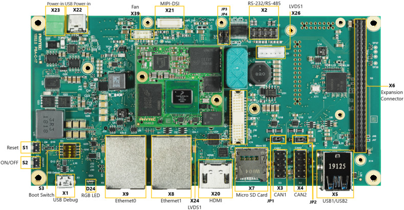
Libra Components (top)
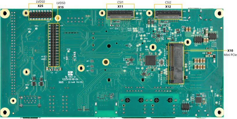
Libra Components (bottom)
2. Getting Started
The phyFLEX-AM62L FPSC Kit is shipped with a pre-flashed SD card. It contains the phytec-qt6demo-image and can be used directly as a boot source. The e.MMC is programmed with only a U-Boot by default. You can get all sources from the BSP downloads page. This chapter explains how to flash a BSP image to SD card and how to start the board.
There are several ways to flash an image to SD card or even e.MMC. Most notably
using simple, sequential writing with the Linux command line tool dd. An
alternative way is to use PHYTEC’s system initialization program called
partup, which makes it especially easy to
format more complex systems. You can get prebuilt Linux binaries of partup from its release page. Also read
partup’s README for installation
instructions.
2.1. Get the Image
The image contains all necessary files and makes sure partitions and any raw
data are correctly written. Both the partup package and the WIC image, which can
be flashed using dd, can be downloaded from our BSP downloads page.
Note that you can find different image versions and variants on our download server. The images are located on the server by folders per “BSP-Version”, “Distro-Name” and “Machine-Name”.
Example to download a partup package and a WIC image from the download server:
host:~$ wget https://download.phytec.de/Software/Linux/BSP-Yocto-AM62Lx/BSP-Yocto-Ampliphy-AM62Lx-ALPHA2/images/ampliphy-vendor/am62lxx-libra-fpsc-1/phytec-qt6demo-image-am62lxx-libra-fpsc-1.rootfs.partup
host:~$ wget https://download.phytec.de/Software/Linux/BSP-Yocto-AM62Lx/BSP-Yocto-Ampliphy-AM62Lx-ALPHA2/images/ampliphy-vendor/am62lxx-libra-fpsc-1/phytec-qt6demo-image-am62lxx-libra-fpsc-1.rootfs.wic.xz
Note
For e.MMC, more complex partitioning schemes or even just large images, we
recommend using the partup package, as it is faster in writing than dd
and allows for a more flexible configuration of the target flash device.
2.2. Write the Image to SD Card
Warning
To create your bootable SD card, you must have root privileges on your Linux host PC. Be very careful when specifying the destination device! All files on the selected device will be erased immediately without any further query!
Selecting the wrong device may result in data loss and e.g. could erase your currently running system on your host PC!
2.2.1. Finding the Correct Device
To create your bootable SD card, you must first find the correct device name of your SD card and possible partitions. If any partitions of the SD cards are mounted, unmount those before you start copying the image to the SD card.
In order to get the correct device name, remove your SD card and execute:
host:~$ lsblkNow insert your SD card and execute the command again:
host:~$ lsblkCompare the two outputs to find the new device names listed in the second output. These are the device names of the SD card (device and partitions if the SD card was formatted).
In order to verify the device names being found, execute the command
sudo dmesg. Within the last lines of its output, you should also find the device names, e.g./dev/sdeor/dev/mmcblk0(depending on your system).
Alternatively, you may use a graphical program of your choice, like GNOME Disks or KDE Partition Manager, to find the correct device.
Now that you have the correct device name, e.g. /dev/sde,
you can see the partitions which must be unmounted if the SD card is formatted.
In this case, you will also find the device name with an appended number
(e.g. /dev/sde1) in the output. These represent the partitions. Some Linux
distributions automatically mount partitions when the device gets plugged in.
Before writing, however, these need to be unmounted to avoid data corruption.
Unmount all those partitions, e.g.:
host:~$ sudo umount /dev/sde1
host:~$ sudo umount /dev/sde2
Now, the SD card is ready to be flashed with an image, using either partup,
dd or bmaptool.
2.2.2. Using bmaptool
One way to prepare an SD card is using
bmaptool. Yocto
automatically creates a block map file (<IMAGENAME>-<MACHINE>.wic.bmap) for
the WIC image that describes the image content and includes checksums for data
integrity. bmaptool is packaged by various Linux distributions. For
Debian-based systems install it by issuing:
host:~$ sudo apt install bmap-tools
Flash a WIC image to SD card by calling:
host:~$ bmaptool copy phytec-qt6demo-image-am62lxx-libra-fpsc-1?(.rootfs).wic?(.xz) /dev/<your_device>
Replace <your_device> with your actual SD card’s device name found previously,
and make sure to place the file <IMAGENAME>-<MACHINE>.wic.bmap alongside
the regular WIC image file, so bmaptool knows which blocks to write and which
to skip.
Warning
bmaptool only overwrites the areas of an SD card where image data is located. This means that a previously written U-Boot environment may still be available after writing the image.
2.2.3. Using partup
Writing to an SD card with partup is done in a single command:
host:~$ sudo partup install phytec-qt6demo-image-am62lxx-libra-fpsc-1?(.rootfs).partup /dev/<your_device>
Make sure to replace <your_device> with your actual device name found previously.
Further usage of partup is explained at its official documentation website.
Warning
Host systems which are using resize2fs version 1.46.6 and older (e.g. Ubuntu 22.04) are not able to write partup packages created with Yocto Mickledore or newer to SD-Card. This is due to a new default option in resize2fs which causes an incompatibility. See release notes.
Note
partup has the advantage of allowing to clear specific raw areas in the MMC user area, which is used in our provided partup packages to erase any existing U-Boot environments. This is a known issue bmaptool does not solve, as mentioned in the previous chapter.
Another key advantage of partup over other flashing tools is that it allows configuring MMC specific parts, like writing to eMMC boot partitions, without the need to call multiple other commands when writing.
2.2.4. Using dd
After having unmounted all SD card’s partitions, you can create your bootable SD card.
Some PHYTEC BSPs produce uncompressed images (with filename-extension *.wic), and some others produce compressed images (with filename-extension *.wic.xz).
To flash an uncompressed images (*.wic) use command below:
host:~$ sudo dd if=phytec-qt6demo-image-am62lxx-libra-fpsc-1?(.rootfs).wic of=/dev/<your_device> bs=1M conv=fsync status=progress
Or to flash a compressed images (*.wic.xz) use that command:
host:~$ xzcat phytec-qt6demo-image-am62lxx-libra-fpsc-1?(.rootfs).wic.xz | sudo dd of=/dev/<your_device> bs=1M conv=fsync status=progress
Again, make sure to replace <your_device> with your actual device name found previously.
The parameter conv=fsync forces a sync operation on the device before
dd returns. This ensures that all blocks are written to the SD card and
none are left in memory. The parameter status=progress will print out
information on how much data is and still has to be copied until it is
finished.
2.3. First Start-up
To boot from an SD card, the bootmode switch (S1) needs to be set to the following position:

Insert the SD card
Connect the target and the host with USB-C on (X14) debug USB
Power up the board
3. Building the BSP
This section will guide you through the general build process of the AM62L BSP using Yocto and the phyLinux script. For more information about our meta-layer or Yocto in general visit: Yocto Reference Manual (scarthgap).
3.1. Basic Set-Up
If you have never created a Phytec BSP with Yocto on your computer, you should take a closer look at the chapter BSP Workspace Installation in the Yocto Reference Manual (scarthgap).
3.2. Get the BSP
There are two ways to get the BSP sources. You can download the complete BSP sources from our BSP downloads page; or you can fetch and build it yourself with Yocto. This is particularly useful if you want to make customizations.
The phyLinux script is a basic management tool for PHYTEC Yocto BSP releases written in Python. It is mainly a helper to get started with the BSP sources structure.
Create a fresh project folder, get phyLinux, and make the script executable:
host:~$ mkdir ~/yocto
host:~$ cd yocto/
host:~/yocto$ wget https://download.phytec.de/Software/Linux/Yocto/Tools/phyLinux
host:~/yocto$ chmod +x phyLinux
Warning
A clean folder is important because phyLinux will clean its working directory. Calling phyLinux from a directory that isn’t empty will result in a warning.
Run phyLinux:
host:~/yocto$ ./phyLinux init
Note
On the first initialization, the phyLinux script will ask you to install the Repo tool in your
/usr/local/bindirectory.During the execution of the init command, you need to choose your processor platform (SoC), PHYTEC’s BSP release number, and the hardware (MACHINE) you are working on.
Note
If you cannot identify your board with the information given in the selector, have a look at the invoice for the product. And have a look at the webpage of our BSP.
It is also possible to pass this information directly using command line parameters:
host:~/yocto$ DISTRO=ampliphy-vendor MACHINE=am62lxx-libra-fpsc-1 ./phyLinux init -p am62l-fpsc -r BSP-Yocto-Ampliphy-AM62Lx-ALPHA2
After the execution of the init command, phyLinux will print a few important notes. For example, it will print your git identity, SOC and BSP release which was selected as well as information for the next steps in the build process.
3.2.1. Starting the Build Process
Set up the shell environment variables:
host:~/yocto$ source sources/poky/oe-init-build-env
Note
This needs to be done every time you open a new shell for starting builds.
The current working directory of the shell should change to build/.
Build your image:
host:~/yocto/build$ bitbake phytec-qt6demo-image
Note
For the first build we suggest starting with our smaller non-graphical image phytec-headless-image to see if everything is working correctly.
host:~/yocto/build$ bitbake phytec-headless-image
The first compile process takes about 40 minutes on a modern Intel Core i7. All subsequent builds will use the filled caches and should take about 3 minutes.
3.2.2. BSP Images
All images generated by Bitbake are deployed to
~/yocto/build/deploy*/images/<machine>. The following list shows for
example all files generated for the am62lxx-libra-fpsc-1 machine:
u-boot.img: U-Boot bootloader image
oftree: Default kernel device tree
ti-boot3.bin: First stage bootloader (R5 SPL)
tispl.bin: Secondary program loader (SPL)
bl1.bin: ARM Trusted Firmware binary
bl31.bin: ARM Trusted Firmware binary
fitImage: Linux kernel FIT image
fitImage-its*.its
Image: Linux kernel image
Image.config: Kernel configuration
k3-am62l32-libra-fpsc*.dtb: Kernel device tree file
phytec-qt6demo-image*.tar.gz: Root file system
phytec-qt6demo-image*.rootfs.wic.xz: compressed SD card image
4. Installing the OS
4.1. Bootmode Switch (S1)
Tip
Hardware revision baseboard: 1618.1
The Libra FPSC features a boot switch with four individually switchable ports to select the phyFLEX-AM62L FPSC default bootsource.

eMMC |
SD Card |

SPI NOR |
4.2. Flash e.MMC
For consistency, it is assumed that a TFTP server is configured; More importantly, all generated images, as listed above, are copied to the default /srv/tftp directory. If you do not have this set up, you need to adjust the paths that point to the images being used in the instructions. For instructions on how to set up the TFTP server and directory, see Setup Network Host.
To boot from e.MMC, make sure that the BSP image is flashed correctly to the e.MMC and the bootmode switch (S1) is set to e.MMC.
Warning
When e.MMC and SD card are flashed with the same (identical) image, the UUIDs of the boot partitions are also identical. If the SD card is connected when booting, this leads to non-deterministic behavior as Linux mounts the boot partition based on UUID.
target:~$ blkid
can be run to inspect whether the current setup is affected. If mmcblk2p1
and mmcblk1p1 have an identical UUID, the setup is affected.
4.2.1. Flash e.MMC from Network
AM62L boards have an Ethernet connector and can be updated over a network. Be
sure to set up the development host correctly. The IP needs to be set to
192.168.3.10, the netmask to 255.255.255.0, and a TFTP server needs to be
available. From a high-level point of view, an e.MMC device is like an SD card.
Therefore, it is possible to flash the WIC image (<name>.wic) from
the Yocto build system directly to the e.MMC. The image contains the
bootloader, kernel, device tree, device tree overlays, and root file system.
4.2.1.1. Flash e.MMC via Network in Linux on Host
It is also possible to install the OS at e.MMC from your Linux host. As before, you need a complete image on your host.
Tip
A working network is necessary! Setup Network Host
Show your available image files on the host:
host:~$ ls /srv/tftp
phytec-qt6demo-image-am62lxx-libra-fpsc-1.rootfs.wic.xz
phytec-qt6demo-image-am62lxx-libra-fpsc-1.rootfs.wic.bmap
Send the image with the bmaptool command combined with ssh through the network
to the e.MMC of your device:
host:~$ scp /srv/tftp/phytec-qt6demo-image-am62lxx-libra-fpsc-1.rootfs.wic.* root@192.168.3.11:/tmp && ssh root@192.168.3.11 "bmaptool copy /tmp/phytec-qt6demo-image-am62lxx-libra-fpsc-1.rootfs.wic.xz /dev/mmcblk0"
4.2.1.2. Flash e.MMC via Network in Linux on Target
You can update the e.MMC from your target.
Tip
A working network is necessary! Setup Network Host
Take a compressed or decompressed image with the accompanying block map file *.bmap on the host and send it with ssh through the network to the e.MMC of the target with a one-line command:
target:~$ scp <USER>@192.168.3.10:/srv/tftp/phytec-qt6demo-image-am62lxx-libra-fpsc-1.rootfs.wic.* /tmp && bmaptool copy /tmp/phytec-qt6demo-image-am62lxx-libra-fpsc-1.rootfs.wic.xz /dev/mmcblk0
4.2.1.3. Flash e.MMC from Network in U-Boot on Target
These steps will show how to update the e.MMC via a network.
Tip
This step only works if the size of the image file is less than 1GB due to limited usage of RAM size in the Bootloader after enabling OP-TEE.
Tip
A working network is necessary! Setup Network Host
Uncompress your image
host:~$ unxz /srv/tftp/phytec-headless-image-am62lxx-libra-fpsc-1.rootfs.wic.xz
Load your image via network to RAM:
when using dhcp
u-boot=> dhcp phytec-headless-image-am62lxx-libra-fpsc-1.rootfs.wic
BOOTP broadcast 1
DHCP client bound to address 192.168.3.1 (1 ms)
Using ethernet@30be0000 device
TFTP from server 192.168.3.10; our IP address is 192.168.3.1
Filename 'phytec-headless-image-am62lxx-libra-fpsc-1.rootfs.wic'.
Load address: 0x40480000
Loading: ######################################
         ######################################
         ######################################
         ...
         ...
         ...
         ######################################
         #############
         11.2 MiB/s
done
Bytes transferred = 911842304 (36599c00 hex)
when using a static ip address (serverip and ipaddr must be set additionally).
u-boot=> tftp ${loadaddr} phytec-headless-image-am62lxx-libra-fpsc-1.rootfs.wic
Using ethernet@30be0000 device
TFTP from server 192.168.3.10; our IP address is 192.168.3.11
Filename 'phytec-headless-image-am62lxx-libra-fpsc-1.rootfs.wic'.
Load address: 0x40480000
Loading: ######################################
         ######################################
         ######################################
         ...
         ...
         ...
         ######################################
         #############
         11.2 MiB/s
done
Bytes transferred = 911842304 (36599c00 hex)
Write the image to the e.MMC:
u-boot=> mmc dev 0
switch to partitions #0, OK
mmc0(part 0) is current device
u-boot=> setexpr nblk ${filesize} / 0x200
u-boot=> mmc write ${loadaddr} 0x0 ${nblk}

MMC write: dev # 0, block # 0, count 1780942 ... 1780942 blocks written: OK
4.2.2. Flash e.MMC from USB stick
4.2.2.1. Flash e.MMC from USB in Linux
These steps will show how to flash the e.MMC on Linux with a USB stick. You only need a complete image saved on the USB stick and a bootable WIC image. (e.g. phytec-qt6demo-image-am62lxx-libra-fpsc-1.|yocto-imageext|). Set the bootmode switch (S1) to SD card.
Insert and mount the USB stick:
[   60.458908] usb-storage 1-1.1:1.0: USB Mass Storage device detected
[   60.467286] scsi host0: usb-storage 1-1.1:1.0
[   61.504607] scsi 0:0:0:0: Direct-Access                               8.07 PQ: 0 ANSI: 2
[   61.515283] sd 0:0:0:0: [sda] 3782656 512-byte logical blocks: (1.94 GB/1.80 GiB)
[   61.523285] sd 0:0:0:0: [sda] Write Protect is off
[   61.528509] sd 0:0:0:0: [sda] No Caching mode page found
[   61.533889] sd 0:0:0:0: [sda] Assuming drive cache: write through
[   61.665969]  sda: sda1
[   61.672284] sd 0:0:0:0: [sda] Attached SCSI removable disk
target:~$ mount /dev/sda1 /mnt
Now show your saved image files on the USB Stick:
target:~$ ls /mnt
phytec-qt6demo-image-am62lxx-libra-fpsc-1.rootfs.wic.xz
phytec-qt6demo-image-am62lxx-libra-fpsc-1.rootfs.wic.bmap
Write the image to the phyFLEX-AM62L FPSC e.MMC (MMC device 2 without partition):
target:~$ bmaptool copy /mnt/phytec-qt6demo-image-am62lxx-libra-fpsc-1.rootfs.wic.xz /dev/mmcblk0
After a complete write, your board can boot from e.MMC.
Tip
Before this will work, you need to configure the bootmode switch (S1) to eMMC.
4.2.2.2. Flash e.MMC from USB stick in U-Boot on Target
Tip
This step only works if the size of the image file is less than 1GB due to limited usage of RAM size in the Bootloader after enabling OPTEE.
These steps will show how to update the e.MMC via a USB device. Configure the bootmode switch (S1) to SD card and insert an SD card. Power on the board and stop in U-Boot prompt. Insert a USB device with the copied uncompressed WIC image to the USB slot.
Load your image from the USB device to RAM:
u-boot=> usb start
starting USB...
USB0:   USB EHCI 1.00
scanning bus 0 for devices... 2 USB Device(s) found
       scanning usb for storage devices... 1 Storage Device(s) found
u-boot=> fatload usb 0:1 0x58000000 phytec-headless-image-am62lxx-libra-fpsc-1.rootfs.wic
497444864 bytes read in 31577 ms (15 MiB/s)
Write the image to the e.MMC:
u-boot=> mmc dev 0
switch to partitions #0, OK
mmc0(part 0) is current device
u-boot=> setexpr nblk ${filesize} / 0x200
u-boot=> mmc write 0x58000000 0x0 ${nblk}

MMC write: dev # 0, block # 0, count 1024000 ... 1024000 blocks written: OK
u-boot=> boot
4.2.3. Flash e.MMC from SD card
Even if there is no network available, you can update the e.MMC. For that, you
only need a ready-to-use image file (*.wic) located on the SD card.
Because the image file is quite large, you need to allocate more SD card space.
To create a new partition or enlarge your SD card, see Resizing ext4 Root Filesystem.
Alternatively, flash a partup package to the SD card, as described in Getting Started. This will ensure the full space of the SD card is used.
4.2.3.1. Flash e.MMC from SD card in Linux on Target
You can also flash the e.MMC on Linux. You only need a partup package or WIC image saved on the SD card.
Show your saved partup package or WIC image files on the SD card:
target:~$ ls
phytec-qt6demo-image-am62lxx-libra-fpsc-1.rootfs.partup
phytec-qt6demo-image-am62lxx-libra-fpsc-1.rootfs.wic.xz
phytec-qt6demo-image-am62lxx-libra-fpsc-1.rootfs.wic.bmap
Write the image to the phyFLEX-AM62L FPSC e.MMC (MMC device 0 without partition) using partup:
target:~$ partup install phytec-qt6demo-image-am62lxx-libra-fpsc-1.rootfs.partup /dev/mmcblk0
Flashing the partup package has the advantage of using the full capacity of the e.MMC device, adjusting partitions accordingly.
Note
Alternatively,
bmaptoolmay be used instead:target:~$ bmaptool copy phytec-qt6demo-image-am62lxx-libra-fpsc-1.rootfs.wic.xz /dev/mmcblk0
Keep in mind that the root partition does not make use of the full space when flashing with
bmaptool.After a complete write, your board can boot from e.MMC.
Warning
Before this will work, you need to configure the bootmode switch (S1) to e.MMC.
4.2.3.2. Flash e.MMC from SD card in U-Boot on Target
Tip
This step only works if the size of the image file is less than 1GB due to limited usage of RAM size in the Bootloader after enabling OPTEE. If the image file is too large use the Updating e.MMC from SD card in Linux on Target subsection.
Flash an SD card with a working image and create a third ext4 partition. Copy the WIC image (for example phytec-qt6demo-image.rootfs.wic) to this partition.
Configure the bootmode switch (S1) to SD card and insert the SD card.
Power on the board and stop in U-Boot.
Load the image:
u-boot=> ext4load mmc 1:3 ${loadaddr} phytec-headless-image-am62lxx-libra-fpsc-1.rootfs.wic
reading
911842304 bytes read in 39253 ms (22.2 MiB/s)
Switch the mmc dev to e.MMC:
u-boot=> mmc list
FSL_SDHC: 1 (SD)
FSL_SDHC: 0 (eMMC)
u-boot=> mmc dev 0
switch to partitions #0, OK
mmc0(part 0) is current device
Flash your WIC image (for example phytec-qt6demo-image.rootfs.wic) from the SD card to e.MMC. This will partition the card and copy tiboot3.bin, tispl.bin, u-boot.img, Image, dtb, dtbo, and root file system to e.MMC.
u-boot=> setexpr nblk ${filesize} / 0x200
u-boot=> mmc write ${loadaddr} 0x0 ${nblk}

MMC write: dev # 0, block # 0, count 1780942 ... 1780942 blocks written: OK
Power off the board and change the bootmode switch (S1) to e.MMC.
4.3. Flash SPI NOR Flash
The phyFLEX-AM62L FPSCs are optionally equipped with SPI NOR Flash. To boot from SPI Flash, set bootmode switch (S1) to SPI NOR. The SPI Flash is usually quite small. The phyFLEX-AM62L FPSC Kit only has 64MiB SPI NOR flash populated. Only the bootloader and the environment can be stored. The kernel, device tree, and file system are taken from other boot sources.
The SPI NOR flash partition table is defined in the U-Boot device tree. It can be printed with:
u-boot=> => mtd list
SF: Detected mt35xu512aba with page size 256 Bytes, erase size 4 KiB, total 64 MiB
List of MTD devices:
* nor0
  - device: flash@0
  - parent: spi@fc40000
  - driver: jedec_spi_nor
  - path: /bus@f0000/bus@fc00000/spi@fc40000/flash@0
  - type: NOR flash
  - block size: 0x1000 bytes
  - min I/O: 0x1 bytes
  - 0x000000000000-0x000004000000 : "nor0"
          - 0x000000000000-0x000000080000 : "ospi.tiboot3"
          - 0x000000080000-0x000000280000 : "ospi.tispl"
          - 0x000000280000-0x000000680000 : "ospi.u-boot"
          - 0x000000680000-0x0000006c0000 : "ospi.env"
          - 0x0000006c0000-0x000000700000 : "ospi.env.backup"
We have two possibilities for flashing:
Flash SPI NOR with a combined binary, which contains all the necessary files (tiboot3.bin, tispl.bin and u-boot.img) on the correct offsets. A whole SPI NOR device in Linux is always marked as first MTD device (e.g. /dev/mtd0) in U-Boot the device is called nor0.
Flash SPI NOR with separate binaries to the corresponding partition. This can be used when only certain bootloader part needs to be updated.
4.3.1. Flash SPI NOR Flash from Network
The SPI NOR can contain the bootloader and environment to boot from. The arm64 kernel can not decompress itself, the image size extends the SPI NOR flash populated on the phyFLEX-AM62L FPSC.
Tip
A working network is necessary! Setup Network Host
4.3.1.1. Flash SPI NOR from Network in kernel on Target
Copy the image from the host to the target:
host:~$ scp ti-boot-container.img root@192.168.3.11:/root
Find the number of blocks to erase of the U-boot partition:
target:~$ mtdinfo /dev/mtd0
mtd0
Name:                           fc40000.spi.0
Type:                           nor
Eraseblock size:                131072 bytes, 128.0 KiB
Amount of eraseblocks:          512 (67108864 bytes, 64.0 MiB)
Minimum input/output unit size: 1 byte
Sub-page size:                  1 byte
Character device major/minor:   90:0
Bad blocks are allowed:         false
Device is writable:             true
Erase the necessary SPI NOR device/partition and flash it:
target:~$ flash_erase /dev/mtd0 0x0 0
target:~$ flashcp ti-boot-container.img /dev/mtd0
4.3.1.2. Flash SPI NOR from Network in U-Boot on Target
Similar to updating the e.MMC over a network, be sure to set up the development host correctly. The IP needs to be set to 192.168.3.10, the netmask to 255.255.255.0, and a TFTP server needs to be available.
A specially formatted U-Boot image for the SPI NOR flash is used. Ensure you use the correct image file. Load the image over tftp, erase and write the bootloader to the flash:
u-boot=> tftp ${loadaddr} ti-boot-container.img
u-boot=> mtd write nor0 ${loadaddr} 0 ${filesize}
SF: Detected mt35xu512aba with page size 256 Bytes, erase size 4 KiB, total 64 MiB
Writing 3752323 byte(s) at offset 0x00000000
Optinaly erase the environment partition as well. This way, the environment can be written after booting from SPI NOR flash:
u-boot=> mtd erase ospi.env
u-boot=> mtd erase ospi.env.backup
4.3.2. Flash SPI NOR Flash from SD card
The bootloader on SPI NOR flash can be also flashed from SD card.
4.3.2.1. Flash SPI NOR from SD card in kernel on Target
Copy the SPI NOR flash U-boot container to the first partition on the SD card.
Mount the SD card:
target:~$ mount /dev/mmcblk1p1 /mnt
Find the number of blocks to erase of the SPI NOR:
target:~$ mtdinfo /dev/mtd0
mtd0
Name:                           fc40000.spi.0
Type:                           nor
Eraseblock size:                131072 bytes, 128.0 KiB
Amount of eraseblocks:          512 (67108864 bytes, 64.0 MiB)
Minimum input/output unit size: 1 byte
Sub-page size:                  1 byte
Character device major/minor:   90:0
Bad blocks are allowed:         false
Device is writable:             true
Erase the SPI NOR and flash it:
target:~$ flash_erase /dev/mtd0 0x0 0
target:~$ flashcp /mnt/ti-boot-container.img /dev/mtd0
4.3.2.2. Flash SPI NOR from SD card in U-Boot on Target
Copy the SPI NOR flash U-boot container to the first partition on the SD card.
A specially formatted U-boot image for the SPI NOR flash is used. Ensure you use the correct image file. Load the image from the SD card, erase and write the bootloader to the flash:
u-boot=> mmc dev 1
u-boot=> fatload mmc 1:1 ${loadaddr} ti-boot-container.img
u-boot=> mtd write nor0 ${loadaddr} 0 ${filesize}
Optinaly erase the environment partition as well. This way, the environment can be written after booting from SPI NOR flash:
u-boot=> mtd erase ospi.env
u-boot=> mtd erase ospi.env.backup
5. Development
5.1. Standalone Build preparation
In this section, we describe how to build the U-Boot and the Linux kernel without using the Yocto Project. This procedure makes the most sense for development. The U-Boot source code, the Linux kernel, and all other git repositories are available on GitHub.
5.1.1. Git Repositories
Used U-Boot repository:
https://github.com/phytec/u-boot-phytec-ti
Our U-Boot is based on the u-boot-phytec-ti and adds board-specific patches.
Used Linux kernel repository:
https://github.com/phytec/linux-phytec-ti
Our AM62L kernel is based on the linux-phytec-ti kernel.
To find out which u-boot and kernel tags to use for a specific board, have a look at your BSP source folder:
meta-phytec/recipes-kernel/linux/linux-phytec-ti_*.bb
meta-phytec/recipes-bsp/u-boot/u-boot-phytec-ti_*.bb
5.1.2. Get the SDK
You can download the SDK from the SDK downloads page, or build it yourself with Yocto:
Move to the Yocto build directory:
host:~$ source sources/poky/oe-init-build-env
host:~$ bitbake -c populate_sdk phytec-qt6demo-image # or another image
After a successful build the SDK installer is deployed to build/deploy*/sdk.
5.1.3. Install the SDK
Set correct permissions and install the SDK:
host:~$ chmod +x phytec-ampliphy-vendor-glibc-x86_64-phytec-qt6demo-image-aarch64-toolchain-BSP-Yocto-Ampliphy-AM62Lx-ALPHA2.sh
host:~$ ./phytec-ampliphy-vendor-glibc-x86_64-phytec-qt6demo-image-aarch64-toolchain-BSP-Yocto-Ampliphy-AM62Lx-ALPHA2.sh
============================================================================================================
Enter target directory for SDK (default: /opt/ampliphy-vendor/BSP-Yocto-Ampliphy-AM62Lx-ALPHA2):
You are about to install the SDK to "/opt/ampliphy-vendor/BSP-Yocto-Ampliphy-AM62Lx-ALPHA2". Proceed [Y/n]? Y
Extracting SDK...done
Setting it up...done
SDK has been successfully set up and is ready to be used.
5.1.4. Using the SDK
Activate the toolchain for your shell by sourcing the environment-setup file in the toolchain directory:
host:~$ source /opt/ampliphy-vendor/BSP-Yocto-Ampliphy-AM62Lx-ALPHA2/environment-setup-aarch64-phytec-linux
5.1.5. Installing Required Tools
Building Linux and U-Boot out-of-tree requires some additional host tool dependencies to be installed. For Ubuntu you can install them with:
host:~$ sudo apt install bison flex libssl-dev bc libncurses-dev python3 python3-setuptools python3-dev python3-yaml python3-jsonschema python3-pyelftools swig yamllint libgnutls28-dev
Warning
Using the SDK on older host distributions (e.g., Ubuntu 20.04 LTS) with Scarthgap TI-based BSPs can cause issues when building U-Boot or Linux kernel tools for host use. If you encounter an “undefined reference” error, a workaround is to prepend the host’s binutils to the PATH.
host$ export PATH=/usr/bin:$PATH
Run this after sourcing the SDK environment-setup file.
Note, SDK issue has not been observed on newer distributions, such as Ubuntu 22.04, which appear to work without requiring any modifications.
5.2. U-Boot standalone build
5.2.1. Get the source code
Get the U-Boot sources:
host:~$ git clone https://github.com/phytec/u-boot-phytec-ti
To get the correct U-Boot tag you need to take a look at our release notes, which can be found here: release notes
The tag used in this release is called 11.01.02
Check out the needed U-Boot tag:
host:~$ cd ~/u-boot-phytec-ti/
host:~/u-boot-phytec-ti$ git fetch --all --tags
host:~/u-boot-phytec-ti$ git checkout tags/11.01.02
Set up a build environment:
host:~/u-boot-phytec-ti$ source /opt/ampliphy-vendor/BSP-Yocto-Ampliphy-AM62Lx-ALPHA2/environment-setup-aarch64-phytec-linux
5.2.2. Get the needed binaries
To build the bootloader, you need to copy these files to your u-boot-phytec-ti build directory and rename them to fit with mkimage script:
- ARM Trusted firmware binaries:
bl1.bin
bl31.bin
binary blobs
If you already built our BSP with Yocto, you can get the bl1.bin, bl31.bin and binary blobs from the directory mentioned here: BSP Images
Or you can download the files here: https://download.phytec.de/Software/Linux/BSP-Yocto-AM62Lx/BSP-Yocto-Ampliphy-AM62Lx-ALPHA2/images/ampliphy-vendor/am62lxx-libra-fpsc-1/
Warning
Make sure you rename the files you need so that they are compatible with the mkimage tool.
5.2.3. Build the bootloader
Build tiboot3.bin, tispl.bin and u-boot.img:
host:~/u-boot-phytec-ti$ make phycore_am62lx_defconfig
host:~/u-boot-phytec-ti$ make BL1=/path/to/bl1.bin BL31=/path/to/bl31.bin BINMAN_INDIRS=/path/to/binary_blobs
5.2.4. Create bootloader binaries for flashing
5.2.4.1. Use with UDA filesystem mode
To use the newly generated files with UDA filesystem boot. They can be coped to the medium as is. E.g. to test this standalone build with SD-Card boot copy the binaries to the SD-Card boot partition:
host:~/|u-boot-repo-name|$ cp tiboot3.bin tispl.bin u-boot.img /path/to/SD-Card/boot
5.2.4.2. Use with block device
The three binaries can be used with block devices. E.g. eMMC and SPI NOR. Create a combined image of all three:
host:~/u-boot-phytec-ti$ dd if=tiboot3.bin of=ti-boot-container.img conv=fsync
host:~/u-boot-phytec-ti$ dd if=tispl.bin of=ti-boot-container.img seek=1024 conv=fsync
host:~/u-boot-phytec-ti$ dd if=tispl.bin of=ti-boot-container.img seek=5120 conv=fsync
flash to a block device e.g. eMMC:
target:~$ echo 0 > /sys/class/block/mmcblk0boot0/force_ro
target:~$ dd if=ti-boot-container.img of=/dev/mmcblk0boot0 conv=fsync
5.3. Kernel standalone build
5.3.1. Setup sources
The used linux-phytec-ti branch can be found in the release notes
The tag needed for this release is called v6.12.35-11.01.05-phy
Check out the needed linux-phytec-ti tag:
host:~$ git clone https://github.com/phytec/linux-phytec-ti
host:~$ cd ~/linux-phytec-ti/
host:~/linux-phytec-ti$ git fetch --all --tags
host:~/linux-phytec-ti$ git checkout tags/v6.12.35-11.01.05-phy
For committing changes, it is highly recommended to switch to a new branch:
host:~/linux-phytec-ti$ git switch --create <new-branch>
Set up a build environment:
host:~/linux-phytec-ti$ source /opt/ampliphy-vendor/BSP-Yocto-Ampliphy-AM62Lx-ALPHA2/environment-setup-aarch64-phytec-linux
5.3.2. Build the kernel
Build the linux kernel:
host:~/linux-phytec-ti$ make phytec_ti_defconfig
host:~/linux-phytec-ti$ make -j$(nproc)
Install kernel modules to e.g. NFS directory:
host:~/linux-phytec-ti$ make INSTALL_MOD_PATH=/home/<user>/<rootfspath> modules_install
The Image can be found at ~/linux-phytec-ti/arch/arm64/boot/Image
The dtb can be found at ~/linux-phytec-ti/arch/arm64/boot/dts/ti/k3-am62l3-libra-rdk-fpsc.dtb
For (re-)building only Devicetrees and -overlays, it is sufficient to run
host:~/linux-phytec-ti$ make dtbs
Note
If you are facing the following build issue:
scripts/dtc/yamltree.c:9:10: fatal error: yaml.h: No such file or directory
Make sure you installed the package “libyaml-dev” on your host system:
host:~$ sudo apt install libyaml-dev
5.3.3. Copy Kernel to SD Card
When one-time boot via netboot is not sufficient, the kernel along with its modules and the corresponding device tree blob may be copied directly to a mounted SD card.
host:~/linux-phytec-ti$ cp arch/arm64/boot/Image /path/to/sdcard/boot/
host:~/linux-phytec-ti$ cp arch/arm64/boot/dts/ti/k3-am62l3-libra-rdk-fpsc.dtb /path/to/sdcard/boot/oftree
host:~/linux-phytec-ti$ make INSTALL_MOD_PATH=/path/to/sdcard/root/ modules_install
5.4. Host Network Preparation
For various tasks involving a network in the Bootloader, some host services are required to be set up. On the development host, a TFTP, NFS and DHCP server must be installed and configured. The following tools will be needed to boot via Ethernet:
host:~$ sudo apt install tftpd-hpa nfs-kernel-server kea
5.4.1. TFTP Server Setup
First, create a directory to store the TFTP files:
host:~$ sudo mkdir /srv/tftp
Then copy your BSP image files to this directory and make sure other users have read access to all the files in the tftp directory, otherwise they are not accessible from the target.
host:~$ sudo chmod -R o+r /srv/tftp
You also need to configure a static IP address for the appropriate interface. The default IP address of the PHYTEC evaluation boards is 192.168.3.11. Setting a host address 192.168.3.10 with netmask 255.255.255.0 is a good choice.
host:~$ ip addr show <network-interface>
Replace <network-interface> with the network interface you configured and want to connect the board to. You can show all network interfaces by not specifying a network interface.
The message you receive should contain this:
inet 192.168.3.10/24 brd 192.168.3.255
Create or edit the
/etc/default/tftpd-hpafile:# /etc/default/tftpd-hpa TFTP_USERNAME="tftp" TFTP_DIRECTORY="/srv/tftp" TFTP_ADDRESS=":69" TFTP_OPTIONS="-s -c"
Set TFTP_DIRECTORY to your TFTP server root directory
Set TFTP_ADDRESS to the host address the server is listening to (set to 0.0.0.0:69 to listen to all local IPs)
Set TFTP_OPTIONS, the following command shows the available options:
host:~$ man tftpd
Restart the services to pick up the configuration changes:
host:~$ sudo service tftpd-hpa restart
Now connect the ethernet port of the board to your host system. We also need a network connection between the embedded board and the TFTP server. The server should be set to IP 192.168.3.10 and netmask 255.255.255.0.
5.4.1.1. NFS Server Setup
Create an nfs directory:
host:~$ sudo mkdir /srv/nfs
Temporarily export the nfs directory: The NFS server is not restricted to a certain file system location, so all we have to do is to export our root file system to the embedded network. In this example, the whole directory is exported and the “lab network” address of the development host is 192.168.3.10. The IP address has to be adapted to the local needs:
host:~$ sudo exportfs -i -o rw,no_root_squash,sync,no_subtree_check 192.168.3.0/255.255.255.0:/srv/nfs
unexport the rootfs when finished:
host:~$ sudo exportfs -u 192.168.3.0/255.255.255.0:/srv/nfs
5.4.1.1.1. Permanent export
To make the export persistent across reboots on most distributions, modify the
/etc/exportsfile and export it:/srv/nfs 192.168.3.0/255.255.255.0(rw,no_root_squash,sync,no_subtree_check)
Now the NFS-Server has to read the
/etc/exportfsfile again:host:~$ sudo exportfs -ra
5.4.1.2. DHCP Server setup
Create or edit the
/etc/kea/kea-dhcp4.conffile; Using the internal subnet sample. Replace <network-interface> with the name for the physical network interface:{ "Dhcp4": { "interfaces-config": { "interfaces": [ "<network-interface>/192.168.3.10" ] }, "lease-database": { "type": "memfile", "persist": true, "name": "/tmp/dhcp4.leases" }, "valid-lifetime": 28800, "subnet4": [{ "id": 1, "next-server": "192.168.3.10", "subnet": "192.168.3.0/24", "pools": [ { "pool": "192.168.3.1 - 192.168.3.255" } ] }] } }
Warning
Be careful when creating subnets as this may interfere with the company
network policy. To be on the safe side, use a different network and specify
that via the interfaces configuration option.
Now the DHCP-Server has to read the
/etc/kea/kea-dhcp4.conffile again:host:~$ sudo systemctl restart kea-dhcp4-server
When you boot/restart your host PC and don’t have the network interface, as specified in the kea-dhcp4 config, already active the kea-dhcp4-server will fail to start. Make sure to start/restart the systemd service when you connect the interface.
Note
DHCP server setup is only needed when using dynamic IP addresses. For our vendor BSPs, static IP addresses are used by default.
u-boot=> env print ip_dyn
ip_dyn=no
To use dynamic IP addresses for netboot, ip_dyn needs to be set to yes.
5.5. Booting the Kernel from a Network
Booting from a network means loading the kernel and device tree over TFTP and the root file system over NFS. The bootloader itself must already be loaded from another available boot device.
5.5.1. Place Images on Host for Netboot
Copy the kernel fitImage, which already contains device-tree and all device-tree overlays to your tftp directory:
host:~$ cp fitImage /srv/tftp
Copy the booting script to your tftp directory:
host:~$ cp net_boot_fit.scr.uimg /srv/tftp
Make sure other users have read access to all the files in the tftp directory, otherwise they are not accessible from the target:
host:~$ sudo chmod -R o+r /srv/tftp
Extract the rootfs to your nfs directory:
host:~$ sudo tar -xvzf phytec-qt6demo-image-am62lxx-libra-fpsc-1.tar.xz -C /srv/nfs
Note
Make sure you extract with sudo to preserve the correct ownership.
5.5.2. Set appropriate U-boot variables
Since the nfsroot directory could be different in other networks, we do not set any default values. Enter the following commands to modify the bootloader environment.
u-boot=> setenv nfsroot /srv/nfs
Set any overlay configurations needed:
u-boot=> setenv overlays overlay.dtbo
5.5.3. Booting from an Embedded Board
Set the correct boot target, if not already set by u-boot board code and boot into network boot:
u-boot=> setenv boot_targets dhcp
u-boot=> boot
5.5.4. Network Settings on Target
To customize the targets ethernet configuration, please follow the description here: Network Environment Customization
5.6. Accessing the Development states
5.6.1. Development state of current release
These release manifests exist to give you access to the development states of the Yocto BSP. They will not be displayed in the phyLinux selection menu but need to be selected manually. This can be done using the following command line:
host:~$ ./phyLinux init -p am62l-fpsc -r BSP-Yocto-Ampliphy-AM62Lx-FPSC-PD25.1.y
This will initialize a BSP that will track the latest development state of the current release (BSP-Yocto-Ampliphy-AM62Lx-ALPHA2). From now on repo sync in this folder will pull all the latest changes from our Git repositories:
host:~$ repo sync
5.6.2. Development state of upcoming release
Also development states of upcoming releases can be accessed this way.
For this execute the following command and look for a release with a higher
PDXX.Y number than the latest one (BSP-Yocto-Ampliphy-AM62Lx-ALPHA2) and .y at the
end:
host:~$ ./phyLinux init -p am62l-fpsc
5.7. Accessing the Latest Upstream Support
We have a vanilla manifest that makes use of the Yocto master branches (not a vendor release), Linux, and U-Boot. This can be used to test the latest upstream kernel/U-Boot.
Note
The master manifest reflects the latest state of development. This tends to be broken from time to time. We try to fix the master on a regular basis.
host:~$ ./phyLinux init -p am62l-fpsc -r BSP-Yocto-Ampliphy-AM62Lx-master
5.8. Format SD card
Most images are larger than the default root partition. To flash any storage device with SD Card, the rootfs needs to be expanded or a separate partition needs to be created. There are some different ways to format the SD Card. The easiest way to do this is to use the UI program Gparted.
5.8.1. Gparted
Get GParted:
host:~$ sudo apt install gparted
Insert the SD card into your host and get the device name:
host:~$ dmesg | tail
...
[30436.175412] sd 4:0:0:0: [sdb] 62453760 512-byte logical blocks: (32.0 GB/29.8 GiB)
[30436.179846]  sdb: sdb1 sdb2
...
Unmount all SD card partitions.
Launch GParted:
host:~$ sudo gparted
5.8.1.1. Expand rootfs
Warning
Running gparted on host systems which are using resize2fs version 1.46.6 and older (e.g. Ubuntu 22.04) are not able to expand the ext4 partition created with Yocto Mickledore and newer. This is due to a new default option in resize2fs which causes a incompatibility. See release notes.
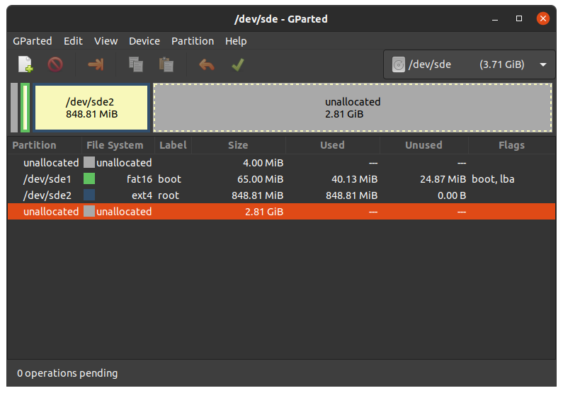
Choose your SD card device at the drop-down menu on the top right
Choose the ext4 root partition and click on resize:
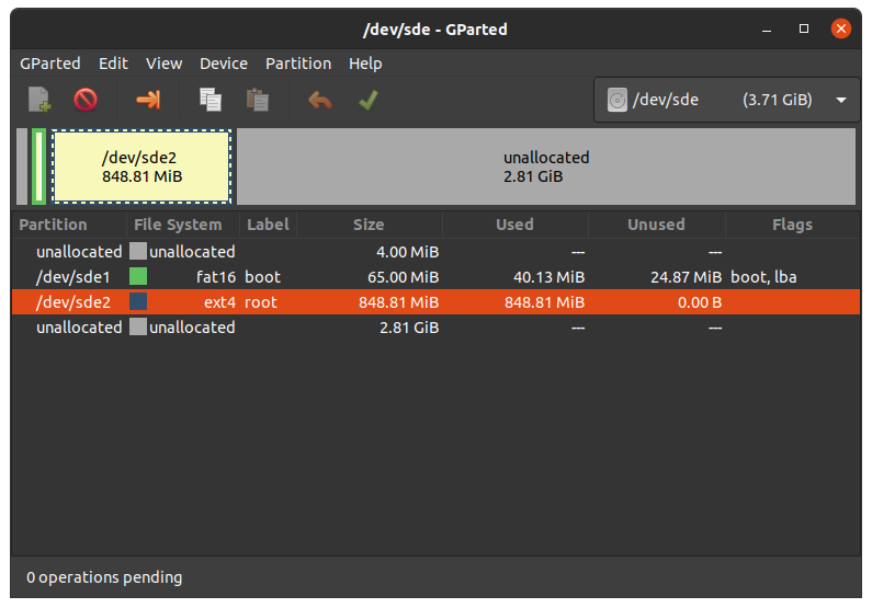
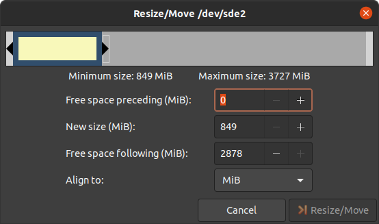
Drag the slider as far as you like or enter the size manually.
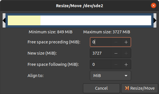
Confirm your entry by clicking on the “Change size” button.
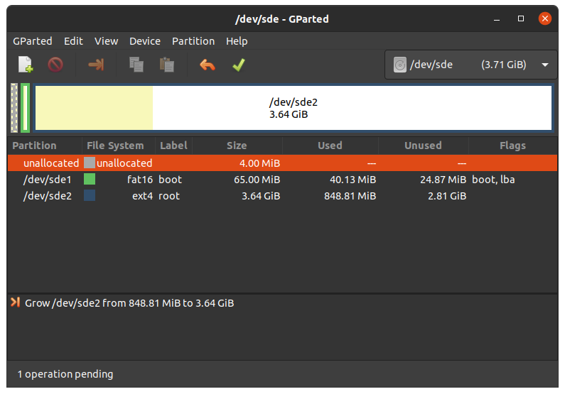
To apply your changes, press the green tick.
Now you can mount the root partition and copy e.g. the phytec-qt6demo-image-am62lxx-libra-fpsc-1.wic image to it. Then unmount it again:
host:~$ sudo cp phytec-qt6demo-image-am62lxx-libra-fpsc-1.wic /mnt/ ; sync
host:~$ umount /mnt
5.8.1.2. Create the Third Partition
Choose your SD card device at the drop-down menu on the top right
Choose the bigger unallocated area and press “New”:
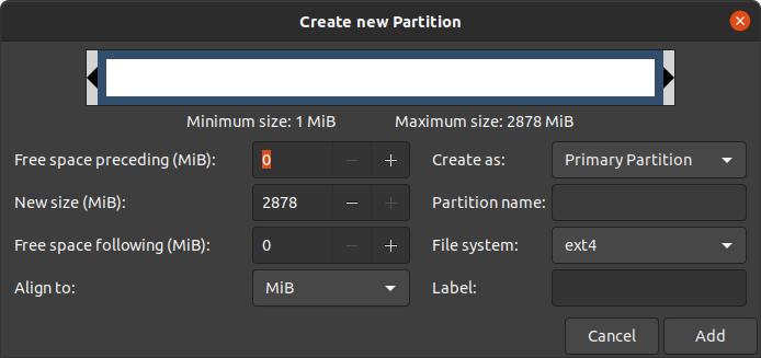
Click “Add”
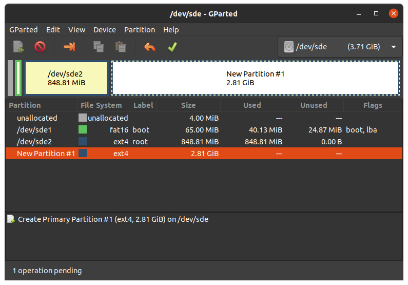
Confirm your changes by pressing the green tick.
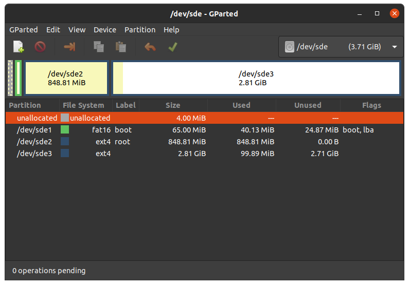
Now you can mount the new partition and copy e.g. phytec-qt6demo-image-am62lxx-libra-fpsc-1.wic image to it. Then unmount it again:
host:~$ sudo mount /dev/sde3 /mnt
host:~$ sudo cp phytec-qt6demo-image-am62lxx-libra-fpsc-1.wic /mnt/ ; sync
host:~$ umount /mnt
6. Device Tree (DT)
6.1. Introduction
The following text briefly describes the Device Tree and can be found in the Linux kernel Documentation (https://docs.kernel.org/devicetree/usage-model.html)
“The “Open Firmware Device Tree”, or simply Devicetree (DT), is a data structure and language for describing hardware. More specifically, it is a description of hardware that is readable by an operating system so that the operating system doesn’t need to hard code details of the machine.”
The kernel documentation is a really good source for a DT introduction. An overview of the device tree data format can be found on the device tree usage page at devicetree.org.
6.2. PHYTEC AM62L BSP Device Tree Concept
The following sections explain some rules PHYTEC has defined on how to set up device trees for our AM62L SoC-based boards.
6.2.1. Device Tree Structure
Module.dtsi - Module includes all devices mounted on the SoM, such as PMIC and RAM.
Board.dts - include the module dtsi file. Devices that come from the AM62L SoC but are just routed down to the carrier board and used there are included in this dts.
Overlay.dtso - enable/disable features depending on optional hardware that may be mounted or missing on SoM or baseboard (e.g SPI flash or PEB-AV-10)
From the root directory of the Linux Kernel our devicetree files for AM62
platforms can be found in arch/arm64/boot/dts/freescale/.
6.2.2. Device Tree Overlay
Device Tree overlays are device tree fragments that can be merged into a device
tree during boot time. These are for example hardware descriptions of an
expansion board. They are instead of being added to the device tree as an extra
include, now applied as an overlay. They also may only contain setting the
status of a node depending on if it is mounted or not. The device tree overlays
are placed next to the other device tree files in our Linux kernel repository in
the folder arch/arm64/boot/dts/freescale/.
Available overlays for am62lxx-libra-fpsc-1.conf are:
k3-am62l3-libra-fpsc-lvds-ac209.dtbo
Otherwise you can show the content of a FIT image including all overlay configs in the FIT image with this command in Linux:
host:~$ dumpimage -l /boot/fitImage
or in U-Boot:
u-boot=> load mmc ${mmcdev}:1 ${loadaddr} fitImage
u-boot=> iminfo
The usage of overlays can be configured during runtime in Linux or U-Boot. Overlays are applied during the boot process in the bootloader after the boot command is called and before the kernel is loaded. The next sections explain the configuration in more detail.
6.2.2.1. Set ${overlays} variable
The ${overlays} U-Boot environment variable contains a number-sign (#)
separated list of overlays that will be applied during boot. The overlays
listed in the overlays variable must be included in the FIT image. Overlays set
in the $KERNEL_DEVICETREE Yocto machine variable will automatically be added to
the FIT image.
The ${overlays} variable can either be set directly in the U-Boot
environment or can be part of the external bootenv.txt environment file.
When desired to use the overlays variable as set manually in the U-Boot
environment, disable bootenv by setting env set no_bootenv 1 as the overlays
variable may be overwritten during the execution of the boot script.
By default, the ${overlays} variable comes from the external bootenv.txt
environment file which is located in the boot partition.
You can read and write the file on booted target from linux:
target:~$ cat /boot/bootenv.txt
overlays=conf-k3-am62l3-libra-rdk-fpsc-peb-eval-01.dtbo#conf-|dtbo-peb-av-10|
Changes will take effect after the next reboot. If no bootenv.txt file is
available the overlays variable can be set directly in the U-Boot environment.
u-boot=> setenv overlays conf-|dtbo-peb-av-10|
u-boot=> printenv overlays
overlays=conf-|dtbo-peb-av-10|
u-boot=> boot
If a user defined ${overlays} variable should be directly loaded from U-Boot
environment but there is still an external bootenv.txt available, the ${no_bootenv}
variable needs to be set as a flag:
u-boot=> setenv no_bootenv 1
u-boot=> setenv overlays conf-|dtbo-peb-av-10|
u-boot=> boot
More information about the external environment can be found in U-boot External Environment subsection of the device tree overlay section.
We use the ${overlays} variable for overlays describing expansion boards and
cameras that can not be detected during run time. To prevent applying overlays
unset the overlays variable and set no_bootenv to anything other than 0.
u-boot=> env delete overlays
u-boot=> env set no_bootenv 1
If desired to use the bootenv.txt file for setting U-Boot variables other than overlays and having overlays disabled, remove the overlays definition line from the bootenv.txt file instead of setting no_bootenv.
6.2.2.2. SoM Variants
Additional overlays are applied automatically to disable components that are not populated on the SoM. The detection is done with the EEPROM data (EEPROM SoM Detection) found on the SoM i2c EEPROM.
It depends on the SoM variant if any device tree overlays will be applied. To check if an overlay will be applied on the running SoM in U-Boot, run:
u-boot=> env print fit_extensions
If the EEPROM data is not available, no device tree overlays are applied.
To prevent application of the SoM variant related overlays the
${no_extensions} variable can be set to 1 in the bootloader environment:
u-boot=> setenv no_extensions 1
u-boot=> boot
6.2.3. U-boot External Environment
During the start of the Linux Kernel the external environment bootenv.txt
text file will be loaded from the boot partition of an MMC device or via TFTP.
The main intention of this file is to store the ${overlays} variable. This makes
it easy to pre-define the overlays in Yocto depending on the used machine. The
content from the file is defined in the Yocto recipe bootenv found in
meta-phytec:
https://github.com/phytec/meta-phytec/tree/scarthgap/recipes-bsp/bootenv
Other variables can be set in this file, too. They will overwrite the existing
settings in the environment. But only variables evaluated after issuing the boot
command can be overwritten, such as ${nfsroot} or ${mmcargs}. Changing other
variables in that file will not have an effect. See the usage during netboot as
an example.
If the external environment can not be loaded the boot process will be anyway continued with the values of the existing environment settings.
6.2.4. Change U-boot Environment from Linux on Target
Libubootenv is a tool included in our images to modify the U-Boot environment of Linux on the target machine.
Print the U-Boot environment using the following command:
target:~$ fw_printenv
Modify a U-Boot environment variable using the following command:
target:~$ fw_setenv <variable> <value>
Caution
Libubootenv takes the environment selected in a configuration file. The environment to use is inserted there, and by default it is configured to use the eMMC environment (known as the default used environment).
If the eMMC is not flashed or the eMMC environment is deleted, libubootenv
will not work. You should modify the /etc/fw_env.config file to match the
environment source that you want to use.
7. Accessing Peripherals
To find out which boards and modules are supported by the release of PHYTEC’s phyFLEX-AM62L FPSC BSP described herein, visit our BSP web page and click the corresponding BSP release in the download section. Here you can find all hardware supported in the columns “Hardware Article Number” and the correct machine name in the corresponding cell under “Machine Name”.
To achieve maximum software reuse, the Linux kernel offers a sophisticated
infrastructure that layers software components into board-specific parts. The
BSP tries to modularize the kit features as much as possible. When a customized
baseboard or even a customer-specific module is developed, most of the software
support can be reused without error-prone copy-and-paste. The kernel code
corresponding to the boards can be found in device trees (DT) in the kernel
repository under arch/arm64/boot/dts/freescale/*.dts.
In fact, software reuse is one of the most important features of the Linux kernel, especially of the ARM implementation which always has to fight with an insane number of possibilities of the System-on-Chip CPUs. The whole board-specific hardware is described in DTs and is not part of the kernel image itself. The hardware description is in its own separate binary, called the Device Tree Blob (DTB) (section device tree).
Please read section PHYTEC AM62L BSP Device Tree Concept to get an understanding of our AM62 BSP device tree model.
The following sections provide an overview of the supported hardware components and their operating system drivers on the AM62 platform. Further changes can be ported upon customer request.
7.1. AM62L Pin Muxing
The AM62L SoC contains many peripheral interfaces. In order to reduce package size and lower overall system cost while maintaining maximum functionality, many of the AM62L terminals can multiplex up to eight signal functions. Although there are many combinations of pin multiplexing that are possible, only a certain number of sets, called IO sets, are valid due to timing limitations. These valid IO sets were carefully chosen to provide many possible application scenarios for the user.
Please refer to our Hardware Manual or the TI AM62L Reference Manual for more information about the specific pins and the muxing capabilities.
The IO set configuration, also called muxing, is done in the Device Tree. The driver pinctrl-single reads the DT’s node fsl,pins, and does the appropriate pin muxing.
The following is an example of the pin muxing of the UART0 device in k3-am62l3-libra-rdk-fpsc.dtsi:
main_uart0_pins_default: main-uart0-default-pins {
   pinctrl-single,pins = <
      AM62LX_IOPAD(0x01b4, PIN_INPUT, 0)      /* (D13) UART0_RXD */
      AM62LX_IOPAD(0x01b8, PIN_OUTPUT, 0)     /* (C13) UART0_TXD */
   >;
   bootph-all;
};
The first argument of the macro AM62LX_IOPAD(pa, val, muxmode) is the pad offset address within the I/O controller (in this example 0x1b4, corresponding UART0_RXD). The second argument (val) specifies the pad configuration, such as input/output and pull-up/pull-down. Third argument (muxmode) selects the functional mux mode for the pad, i.e. which peripheral signal is connected to it. In this case, 0 corresponds to the default mux option for UART0.
The device tree representation for UART0 pinmuxing: https://github.com/phytec/linux-phytec-ti/tree/v6.12.35-11.01.05-phy/arch/arm64/boot/dts/ti/k3-am62l3-libra-rdk-fpsc.dts#L150
7.2. RS232
The FPSC Standard supports 3 UART units. On the Libra FPSC, TTL level signals of UART0 (the standard console) and WKUP_UART0 are routed to a FT4232H UART to USB converter expansion. This USB is brought out at USB-C connector X14. UART4 is connected to a multi-protocol transceiver for RS-232 and RS-485, available at pin header connector X27 at the RS-232 level, or at the RS-485 level. The muxing of the used transceivers is done by switch S5 on the baseboard. For more information about the correct setup please refer to the phyFLEX-AM62L FPSC/Libra FPSC Hardware Manual section UARTs. The switch S5 need to be set correctly.
Display the current settings of a terminal in a human-readable format:
target:~$ stty -a
With a simple echo and cat, basic communication can be tested. Example:
target:~$ echo 123 > /dev/ttyS1
host:~$ cat /dev/ttyUSB2
The device tree representation for RS232: https://github.com/phytec/linux-phytec-ti/tree/v6.12.35-11.01.05-phy/arch/arm64/boot/dts/ti/k3-am62l3-libra-rdk-fpsc.dts#L327
7.3. Network
Libra FPSC-AM62L provides two ethernet interfaces. A gigabit Ethernet is provided by our module and board.
Warning
The naming convention of the Ethernet interfaces in the hardware (ETH0 and ETH1) do not align with the network interfaces (end0 and end1) in Linux. So, be aware of these differences:
All interfaces offer a standard Linux network port that can be programmed using
the BSD socket interface. The whole network configuration is handled by
the systemd-networkd daemon. The relevant configuration files can be found on
the target in /lib/systemd/network/ as well as the BSP in
meta-ampliphy/recipes-core/systemd/systemd-conf.
IP addresses can be configured within *.network files. The interfaces are configured to static IP as default. The default IP address and netmask for end0 is:
end0: 192.168.3.11/24
To configure end0 to dynamic IP over DHCP, go to
/lib/systemd/network/\*-end0.network
and delete the line:
Address=192.168.3.11/24
The DT Ethernet setup might be split into two files depending on your hardware configuration: the module DT and the board-specific DT. The device tree set up for the ethernet where the PHY is populated on the SoM can be found here: https://github.com/phytec/linux-phytec-ti/tree/v6.12.35-11.01.05-phy/arch/arm64/boot/dts/ti/k3-am62l-phycore-fpsc.dtsi#L148 `.
The device tree set up for EQOS Ethernet IP core where the PHY is populated on the Libra FPSC can be found here: https://github.com/phytec/linux-phytec-ti/tree/v6.12.35-11.01.05-phy/arch/arm64/boot/dts/ti/k3-am62l3-libra-rdk-fpsc.dts#L213.
7.3.1. Network Environment Customization
7.3.1.1. U-boot network-environment
To find the Ethernet settings in the target bootloader:
u-boot=> printenv ipaddr serverip netmask
With your development host set to IP 192.168.3.10 and netmask 255.255.255.0, the target should return:
u-boot=> printenv ipaddr serverip netmask
ipaddr=192.168.3.11
serverip=192.168.3.10
netmask=255.225.255.0
If you need to make any changes:
u-boot=> setenv <parameter> <value>
<parameter> should be one of ipaddr, netmask, gatewayip or serverip. <value> will be the actual value of the chosen parameter.
The changes you made are temporary for now. To save these:
u-boot=> saveenv
Here you can also change the IP address to DHCP instead of using a static one.
Configure:
u-boot=> setenv ip dhcp
Set up paths for TFTP and NFS. A modification could look like this:
u-boot=> setenv nfsroot /home/user/nfssrc
Please note that these modifications will only affect the bootloader settings.
Tip
Variables like nfsroot and netargs can be overwritten by the U-boot External
Environment. For netboot, the external environment will be loaded from tftp.
For example, to locally set the nfsroot variable in a bootenv.txt file,
locate the tftproot directory:
nfsroot=/home/user/nfssrc
There is no need to store the info on the target. Please note that this does not work for variables like ipaddr or serveraddr as they need to be already set when the external environment is being loaded.
7.3.1.1.1. Multiple network interfaces in U-Boot
Some boards may have support for multiple network interfaces in U-Boot. U-Boot lists all supported network interfaces during startup. This generic example illustrates support for multiple network interfaces:
Net:
eth0: ethernet@10000000, eth1: ethernet@10010000
There are three environment variables that will contribute to the selection of the ethernet interface for example when loading a file over tftp.
ethrotateDetermines if other interfaces will be probed if the first one fails. Valid values are yes/no. Default is yes if unset.
ethactSets the current active ethernet interface. This interface will be used (first). It is usually unset at boot, but will be set automatically by U-Boot to the last used interface as soon as ethernet is used for the first time. U-Boot will overwrite existing values. Only one ethernet interface can be set, lists are not allowed.
ethprimeThis will determine the preferred ethernet interface if ethact is unset. Otherwise this will be ignored. Only one ethernet interface can be set, lists are not allowed.
Note
The variables ipaddr, serverip and netmask are global and not specific to a
certain ethernet interface, so they might need to be adapted to the ethernet
interface in use.
7.3.1.1.2. Secondary Ethernet Interface Configuration in U-Boot
By default, U-Boot utilizes the Ethernet PHY located on the module. To use the network connection provided by the PHY on the carrier board, configuration changes are required.
To enable the secondary Ethernet interface in U-Boot, the active Ethernet connection must be adjusted. The IP address configuration in U-Boot may also need modification.
Configure the development host with IP address 192.168.4.10 and netmask 255.255.255.0. The target device must then be configured as follows:
u-boot=> setenv ethact eth1
u-boot=> setenv ipaddr 192.168.4.11
7.3.1.2. Kernel network-environment
Find the ethernet settings for end0 in the target kernel:
target:~$ ip -statistics address show end0
2: end0: <NO-CARRIER,BROADCAST,MULTICAST,UP> mtu 1500 qdisc mq state UP group default qlen 1000
    link/ether 50:2d:f4:19:d6:33 brd ff:ff:ff:ff:ff:ff
    RX:  bytes packets errors dropped  missed   mcast
             0       0      0       0       0       0
    TX:  bytes packets errors dropped carrier collsns
             0       0      0       0       0       0
Temporary adaption of the end0 configuration:
target:~$ ip address add 192.168.3.11/24 dev end0
7.4. SD card
The AM62L supports a slot for Secure Digital cards to be used as general-purpose block devices. These devices can be used in the same way as any other block device.
Warning
These kinds of devices are hot-pluggable. Nevertheless, you must ensure not to unplug the device while it is still mounted. This may result in data loss!
After inserting an SD card, the kernel will generate new device nodes in /dev. The full device can be reached via its /dev/mmcblk1 device node. SD card partitions will show up as:
/dev/mmcblk1p<Y>
<Y> counts as the partition number starting from 1 to the max count of partitions on this device. The partitions can be formatted with any kind of file system and also handled in a standard manner, e.g. the mount and umount command work as expected.
Tip
These partition device nodes will only be available if the card contains a valid partition table (”hard disk” like handling). If no partition table is present, the whole device can be used as a file system (”floppy” like handling). In this case, /dev/mmcblk1 must be used for formatting and mounting. The cards are always mounted as being writable.
DT configuration for the MMC (SD card slot) interface can be found here: https://github.com/phytec/linux-phytec-ti/tree/v6.12.35-11.01.05-phy/arch/arm64/boot/dts/ti/k3-am62l-phycore-fpsc.dtsi#L272 and https://github.com/phytec/linux-phytec-ti/tree/v6.12.35-11.01.05-phy/arch/arm64/boot/dts/ti/k3-am62l3-libra-rdk-fpsc.dts#L355
DT configuration for the e.MMC interface can be found here: https://github.com/phytec/linux-phytec-ti/tree/v6.12.35-11.01.05-phy/arch/arm64/boot/dts/ti/k3-am62l-phycore-fpsc.dtsi#L263
7.5. e.MMC Devices
PHYTEC modules like phyFLEX-AM62L FPSC are populated with an e.MMC memory chip as the main storage. e.MMC devices contain raw Multi-Level Cells (MLC) or Triple-Level Cells (TLC) combined with a memory controller that handles ECC and wear leveling. They are connected via an SD/MMC interface to the AM62L and are represented as block devices in the Linux kernel like SD cards, flash drives, or hard disks.
The electric and protocol specifications are provided by JEDEC (https://www.jedec.org/standards-documents/technology-focus-areas/flash-memory-ssds-ufs-emmc/e-mmc). The e.MMC manufacturer’s datasheet is relatively short and meant to be read together with the supported version of the JEDEC e.MMC standard.
PHYTEC currently utilizes the e.MMC chips with JEDEC Version 5.0 and 5.1
7.5.1. Extended CSD Register
e.MMC devices have an extensive amount of extra information and settings that are available via the Extended CSD registers. For a detailed list of the registers, see manufacturer datasheets and the JEDEC standard.
In the Linux user space, you can query the registers:
target:~$ mmc extcsd read /dev/mmcblk0
You will see:
=============================================
   Extended CSD rev 1.7 (MMC 5.0)
=============================================

 Card Supported Command sets [S_CMD_SET: 0x01]
 [...]
7.5.2. Enabling Background Operations (BKOPS)
In contrast to raw NAND Flash, an e.MMC device contains a Flash Transfer Layer (FTL) that handles the wear leveling, block management, and ECC of the raw MLC or TLC. This requires some maintenance tasks (for example erasing unused blocks) that are performed regularly. These tasks are called Background Operations (BKOPS).
By default (depending on the chip), the background operations may or may not be executed periodically, impacting the worst-case read and write latency.
The JEDEC Standard has specified a method since version v4.41 that the host can issue BKOPS manually. See the JEDEC Standard chapter Background Operations and the description of registers BKOPS_EN (Reg: 163) and BKOPS_START (Reg: 164) in the e.MMC datasheet for more details.
Meaning of Register BKOPS_EN (Reg: 163) Bit MANUAL_EN (Bit 0):
Value 0: The host does not support the manual trigger of BKOPS. Device write performance suffers.
Value 1: The host does support the manual trigger of BKOPS. It will issue BKOPS from time to time when it does not need the device.
The mechanism to issue background operations has been implemented in the Linux kernel since v3.7. You only have to enable BKOPS_EN on the e.MMC device (see below for details).
The JEDEC standard v5.1 introduces a new automatic BKOPS feature. It frees the host to trigger the background operations regularly because the device starts BKOPS itself when it is idle (see the description of bit AUTO_EN in register BKOPS_EN (Reg: 163)).
To check whether BKOPS_EN is set, execute:
target:~$ mmc extcsd read /dev/mmcblk0 | grep BKOPS_EN
The output will be, for example:
Enable background operations handshake [BKOPS_EN]: 0x01
#OR
Enable background operations handshake [BKOPS_EN]: 0x00
Where value 0x00 means BKOPS_EN is disabled and device write performance suffers. Where value 0x01 means BKOPS_EN is enabled and the host will issue background operations from time to time.
Enabling can be done with this command:
target:~$ target:~$ mmc --help

[...]
mmc bkops_en <auto|manual> <device>
    Enable the eMMC BKOPS feature on <device>.
    The auto (AUTO_EN) setting is only supported on eMMC 5.0 or newer.
    Setting auto won't have any effect if manual is set.
    NOTE!  Setting manual (MANUAL_EN) is one-time programmable (unreversible) change.
To set the BKOPS_EN bit, execute:
target:~$ mmc bkops_en manual /dev/mmcblk0
To ensure that the new setting is taken over and the kernel triggers BKOPS by itself, shut down the system:
target:~$ poweroff
Tip
The BKOPS_EN bit is one-time programmable only. It cannot be reversed.
7.5.3. Reliable Write
There are two different Reliable Write options:
Reliable Write option for a whole e.MMC device/partition.
Reliable Write for single write transactions.
Tip
Do not confuse e.MMC partitions with partitions of a DOS, MBR, or GPT partition table (see the previous section).
The first Reliable Write option is mostly already enabled on the e.MMCs mounted on the phyFLEX-AM62L FPSC SoMs. To check this on the running target:
target:~$ mmc extcsd read /dev/mmcblk0 | grep -A 5 WR_REL_SET
Write reliability setting register [WR_REL_SET]: 0x1f
 user area: the device protects existing data if a power failure occurs during a write o
peration
 partition 1: the device protects existing data if a power failure occurs during a write
 operation
 partition 2: the device protects existing data if a power failure occurs during a write
 operation
 partition 3: the device protects existing data if a power failure occurs during a write
 operation
 partition 4: the device protects existing data if a power failure occurs during a write
 operation
--
 Device supports writing EXT_CSD_WR_REL_SET
 Device supports the enhanced def. of reliable write
Otherwise, it can be enabled with the mmc tool:
target:~$ mmc --help

[...]
mmc write_reliability set <-y|-n|-c> <partition> <device>
    Enable write reliability per partition for the <device>.
    Dry-run only unless -y or -c is passed.
    Use -c if more partitioning settings are still to come.
    NOTE!  This is a one-time programmable (unreversible) change.
The second Reliable Write option is the configuration bit Reliable Write Request parameter (bit 31) in command CMD23. It has been used in the kernel since v3.0 by file systems, e.g. ext4 for the journal and user space applications such as fdisk for the partition table. In the Linux kernel source code, it is handled via the flag REQ_META.
Conclusion: ext4 file system with mount option data=journal should be safe against power cuts. The file system check can recover the file system after a power failure, but data that was written just before the power cut may be lost. In any case, a consistent state of the file system can be recovered. To ensure data consistency for the files of an application, the system functions fdatasync or fsync should be used in the application.
7.5.4. Resizing ext4 Root Filesystem
When flashing the SD card image to e.MMC the ext4 root partition is not extended to the end of the e.MMC. parted can be used to expand the root partition. The example works for any block device such as e.MMC, SD card, or hard disk.
Get the current device size:
target:~$ parted /dev/mmcblk0 print
The output looks like this:
Model: MMC Q2J55L (sd/mmc)
Disk /dev/mmcblk0: 7617MB
Sect[ 1799.850385]  mmcblk0: p1 p2
or size (logical/physical): 512B/512B
Partition Table: msdos
Disk Flags:

Number  Start   End     Size    Type     File system  Flags
 1      4194kB  72.4MB  68.2MB  primary  fat16        boot, lba
 2      72.4MB  537MB   465MB   primary  ext4
Use parted to resize the root partition to the max size of the device:
target:~$ parted /dev/mmcblk0 resizepart 2 100%
Information: You may need to update /etc/fstab.

target:~$ parted /dev/mmcblk0 print
Model: MMC Q2J55L (sd/mmc)
Disk /dev/mmcblk0: 7617MB
Sector size (logical/physical): 512[ 1974.191657]  mmcblk0: p1 p2
B/512B
Partition Table: msdos
Disk Flags:

Number  Start   End     Size    Type     File system  Flags
 1      4194kB  72.4MB  68.2MB  primary  fat16        boot, lba
 2      72.4MB  7617MB  7545MB  primary  ext4
Resize the filesystem to a new partition size:
target:~$ resize2fs /dev/mmcblk0p2
resize2fs 1.46.1 (9-Feb-2021)
Filesystem at /dev/mmcblk0p2 is mounted on /; on-line resizing required
[ 131.609512] EXT4-fs (mmcblk0p2): resizing filesystem
from 454136 to 7367680 blocks
old_desc_blocks = 4, new_desc_blocks = 57
[ 131.970278] EXT4-fs (mmcblk0p2): resized filesystem to 7367680
The filesystem on /dev/mmcblk0p2 is now 7367680 (1k) blocks long
Increasing the filesystem size can be done while it is mounted. But you can also boot the board from an SD card and then resize the file system on the e.MMC partition while it is not mounted.
7.5.5. Enable pseudo-SLC Mode
e.MMC devices use MLC or TLC (https://en.wikipedia.org/wiki/Multi-level_cell) to store the data. Compared with SLC used in NAND Flash, MLC or TLC have lower reliability and a higher error rate at lower costs.
If you prefer reliability over storage capacity, you can enable the pseudo-SLC mode or SLC mode. The method used here employs the enhanced attribute, described in the JEDEC standard, which can be set for continuous regions of the device. The JEDEC standard does not specify the implementation details and the guarantees of the enhanced attribute. This is left to the chipmaker. For the Micron chips, the enhanced attribute increases the reliability but also halves the capacity.
Warning
When enabling the enhanced attribute on the device, all data will be lost.
The following sequence shows how to enable the enhanced attribute.
First obtain the current size of the e.MMC device with:
target:~$ parted -m /dev/mmcblk0 unit B print
You will receive:
BYT;
/dev/mmcblk0:63652757504B:sd/mmc:512:512:unknown:MMC S0J58X:;
As you can see this device has 63652757504 Byte = 60704 MiB.
To get the maximum size of the device after pseudo-SLC is enabled use:
target:~$ mmc extcsd read /dev/mmcblk0 | grep ENH_SIZE_MULT -A 1
which shows, for example:
Max Enhanced Area Size [MAX_ENH_SIZE_MULT]: 0x000764
i.e. 3719168 KiB
--
Enhanced User Data Area Size [ENH_SIZE_MULT]: 0x000000
i.e. 0 KiB
Here the maximum size is 3719168 KiB = 3632 MiB.
Now, you can set enhanced attribute for the whole device, e.g. 3719168 KiB, by typing:
target:~$ mmc enh_area set -y 0 3719168 /dev/mmcblk0
You will get:
Done setting ENH_USR area on /dev/mmcblk0
setting OTP PARTITION_SETTING_COMPLETED!
Setting OTP PARTITION_SETTING_COMPLETED on /dev/mmcblk0 SUCCESS
Device power cycle needed for settings to take effect.
Confirm that PARTITION_SETTING_COMPLETED bit is set using 'extcsd read' after power cycle
To ensure that the new setting has taken over, shut down the system:
target:~$ poweroffand perform a power cycle. It is recommended that you verify the settings now.
First, check the value of ENH_SIZE_MULT which must be 3719168 KiB:
target:~$ mmc extcsd read /dev/mmcblk0 | grep ENH_SIZE_MULT -A 1
You should receive:
Max Enhanced Area Size [MAX_ENH_SIZE_MULT]: 0x000764
i.e. 3719168 KiB
--
Enhanced User Data Area Size [ENH_SIZE_MULT]: 0x000764
i.e. 3719168 KiB
Finally, check the size of the device:
target:~$ parted -m /dev/mmcblk0 unit B print
BYT;
/dev/mmcblk0:31742492672B:sd/mmc:512:512:unknown:MMC S0J58X:;
7.5.6. Erasing the Device
It is possible to erase the e.MMC device directly rather than overwriting it with zeros. The e.MMC block management algorithm will erase the underlying MLC or TLC or mark these blocks as discard. The data on the device is lost and will be read back as zeros.
After booting from SD card execute:
target:~$ blkdiscard -f --secure /dev/mmcblk0
The option –secure ensures that the command waits until the eMMC device has erased all blocks. The -f (force) option disables all checking before erasing and it is needed when the eMMC device contains existing partitions with data.
Tip
target:~$ dd if=/dev/zero of=/dev/mmcblk0 conv=fsync
also destroys all information on the device, but this command is bad for wear leveling and takes much longer!
7.5.7. e.MMC Boot Partitions
An e.MMC device contains four different hardware partitions: user, boot1, boot2, and rpmb.
The user partition is called the User Data Area in the JEDEC standard and is the main storage partition. The partitions boot1 and boot2 can be used to host the bootloader and are more reliable. Which partition the AM62L uses to load the bootloader is controlled by the boot configuration of the e.MMC device. The partition rpmb is a small partition and can only be accessed via a trusted mechanism.
Furthermore, the user partition can be divided into four user-defined General Purpose Area Partitions. An explanation of this feature exceeds the scope of this document. For further information, see the JEDEC Standard Chapter 7.2 Partition Management.
Tip
Do not confuse e.MMC partitions with partitions of a DOS, MBR, or GPT partition table.
The current PHYTEC BSP does not use the extra partitioning feature of e.MMC devices. The U-Boot is flashed at the beginning of the user partition. The U-Boot environment is placed at a fixed location after the U-Boot. An MBR partition table is used to create two partitions, a FAT32 boot, and ext4 rootfs partition. They are located right after the U-Boot and the U-Boot environment. The FAT32 boot partition contains the kernel and device tree.
With e.MMC flash storage it is possible to use the dedicated boot partitions for redundantly storing the bootloader. The Bootloader environment still resides in the user area before the first partition. The user area also still contains the bootloader which the image first shipped during its initialization process. Below is an example, to flash the bootloader to one of the two boot partitions and switch the boot device via userspace commands.
7.5.7.1. Via userspace Commands
On the host, run:
host:~$ scp <bootloader> root@192.168.3.11:/tmp/
The partitions boot1 and boot2 are read-only by default. To write to them from
user space, you have to disable force_ro in the sysfs.
To manually write the bootloader to the e.MMC boot partitions, first disable the write protection:
target:~$ echo 0 > /sys/block/mmcblk0boot0/force_ro
target:~$ echo 0 > /sys/block/mmcblk0boot1/force_ro
Write the bootloader to the e.MMC boot partitions:
target:~$ dd if=/tmp/<bootloader> of=/dev/mmcblk0boot0
target:~$ dd if=/tmp/<bootloader> of=/dev/mmcblk0boot1
The following table is for the offset of the AM62L SoC:
SoC |
Offset User Area |
Offset Boot Partition |
e.MMC Device |
|---|---|---|---|
AM62L |
32 kiB |
0 kiB |
/dev/mmcblk0 |
After that set the boot partition from user space using the mmc tool:
(for ‘boot0’) :
target:~$ mmc bootpart enable 1 0 /dev/mmcblk0
(for ‘boot1’) :
target:~$ mmc bootpart enable 2 0 /dev/mmcblk0
To disable booting from the e.MMC boot partitions simply enter the following command:
target:~$ mmc bootpart enable 0 0 /dev/mmcblk0
To explicitly enable booting from the e.MMC user area, run:
target:~$ mmc bootpart enable 7 0 /dev/mmcblk0
7.5.7.2. Automatic failover
The ROM loader implements an automatic failover mechanism for e.MMC boot partitions. If booting
from the primary partition fails, the system automatically attempts to boot from the secondary
partition. This failover is indicated by a change in the boot message from
Boot Stage: Primary boot to Boot Stage: Secondary boot.
This functionality is limited to boot0 and boot1 partitions and does not apply to the user area.
7.6. SPI Master
The AM62L controller has MCSPI and an OSPI controllers included. The MCSPI controller supports four SPI channels with each up to 4 devices. The OSPI controllers supports Single/Dual/Quad/Octal mode data transfer (1/2/4/8 bidirectional data lines).
7.6.1. SPI NOR Flash
Libra FPSC is equipped with a QSPI NOR Flash which connects to the AM62L’s OSPI interface.
From Linux userspace, the NOR Flash partitions are accessible via /dev/mtd<N> devices where <N> is the MTD device number associated with the NOR flash partition to access. To find the correct MTD device number for a partition, run on the target:
root@am62lxx-libra-fpsc-1:~$ mtdinfo --all
Count of MTD devices:           5
Present MTD devices:            mtd0, mtd1, mtd2, mtd3, mtd4
Sysfs interface supported:      yes

mtd0
Name:                           ospi.tiboot3
Type:                           nor
Eraseblock size:                131072 bytes, 128.0 KiB
Amount of eraseblocks:          4 (524288 bytes, 512.0 KiB)
Minimum input/output unit size: 1 byte
Sub-page size:                  1 byte
Character device major/minor:   90:0
Bad blocks are allowed:         false
Device is writable:             true

mtd1
Name:                           ospi.tispl
Type:                           nor
Eraseblock size:                131072 bytes, 128.0 KiB
Amount of eraseblocks:          16 (2097152 bytes, 2.0 MiB)
Minimum input/output unit size: 1 byte
Sub-page size:                  1 byte
Character device major/minor:   90:2
Bad blocks are allowed:         false
Device is writable:             true

mtd2
Name:                           ospi.u-boot
Type:                           nor
Eraseblock size:                131072 bytes, 128.0 KiB
Amount of eraseblocks:          32 (4194304 bytes, 4.0 MiB)
Minimum input/output unit size: 1 byte
Sub-page size:                  1 byte
Character device major/minor:   90:4
Bad blocks are allowed:         false
Device is writable:             true

mtd3
Name:                           ospi.env
Type:                           nor
Eraseblock size:                131072 bytes, 128.0 KiB
Amount of eraseblocks:          2 (262144 bytes, 256.0 KiB)
Minimum input/output unit size: 1 byte
Sub-page size:                  1 byte
Character device major/minor:   90:6
Bad blocks are allowed:         false
Device is writable:             true

mtd4
Name:                           ospi.env.backup
Type:                           nor
Eraseblock size:                131072 bytes, 128.0 KiB
Amount of eraseblocks:          2 (262144 bytes, 256.0 KiB)
Minimum input/output unit size: 1 byte
Sub-page size:                  1 byte
Character device major/minor:   90:8
Bad blocks are allowed:         false
Device is writable:             true
It lists all MTD devices and the corresponding partition names. The flash node is defined inside of the SPI master node in the module DTS. The SPI node contains all devices connected to this SPI bus which is in this case only the SPI NOR Flash.
The definition of the SPI master node in the device tree can be found here:
7.7. GPIOs
The Libra FPSC has a set of pins especially dedicated to user I/Os. Those pins are connected directly to AM62L pins and are muxed as GPIOs. They are directly usable in Linux userspace. The processor has organized its GPIOs into nine banks of 16 GPIOs each (up to 144 GPIOs). However, not all GPIOs are pinned out on the Libra FPSC board.
In Linux, the internal GPIO module is exposed as a single GPIO controller, represented by gpiochip0. This controller provides access to all available GPIOs on the device. On the Libra FPSC, this corresponds to 126 GPIO lines in total.
Accessing GPIOs from userspace will be done using the libgpiod. It provides a library and tools for interacting with the Linux GPIO character device. Examples of some usages of various tools:
Detecting the gpiochips on the chip:
target:~$ gpiodetect
gpiochip0 [600000.gpio] (126 lines)
GPIO expander
Beside the GPIOs of the AM62L SoC, the Libra FPSC has a GPIO expander, which adds more GPIOs to the system.
gpiochip2 [4-0020] (16 lines)DT configuration for the GPIO expander can be found here:
Show detailed information about the gpiochips. Like their names, consumers, direction, active state, and additional flags:
target:~$ gpioinfo -c gpiochip0
Read the value of a GPIO (e.g GPIO 20 from chip0):
target:~$ gpioget -c gpiochip0 20
Set the value of GPIO 20 on chip0 to 0 and exit tool:
target:~$ gpioset -z -c gpiochip0 20=0
Help text of gpioset shows possible options:
target:~$ gpioset --help
Usage: gpioset [OPTIONS] <line=value>...

Set values of GPIO lines.

Lines are specified by name, or optionally by offset if the chip option
is provided.
Values may be '1' or '0', or equivalently 'active'/'inactive' or 'on'/'off'.

The line output state is maintained until the process exits, but after that
is not guaranteed.

Options:
      --banner            display a banner on successful startup
  -b, --bias <bias>       specify the line bias
                  Possible values: 'pull-down', 'pull-up', 'disabled'.
                  (default is to leave bias unchanged)
      --by-name           treat lines as names even if they would parse as an offset
  -c, --chip <chip>       restrict scope to a particular chip
  -C, --consumer <name>   consumer name applied to requested lines (default is 'gpioset')
  -d, --drive <drive>     specify the line drive mode
                  Possible values: 'push-pull', 'open-drain', 'open-source'.
                  (default is 'push-pull')
  -h, --help              display this help and exit
  -l, --active-low        treat the line as active low
  -p, --hold-period <period>
                  the minimum time period to hold lines at the requested values
  -s, --strict            abort if requested line names are not unique
  -t, --toggle <period>[,period]...
                  toggle the line(s) after the specified period(s)
                  If the last period is non-zero then the sequence repeats.
      --unquoted  don't quote line names
  -v, --version           output version information and exit
  -z, --daemonize set values then detach from the controlling terminal

Chips:
    A GPIO chip may be identified by number, name, or path.
    e.g. '0', 'gpiochip0', and '/dev/gpiochip0' all refer to the same chip.

Periods:
    Periods are taken as milliseconds unless units are specified. e.g. 10us.
    Supported units are 's', 'ms', and 'us'.

*Note*
    The state of a GPIO line controlled over the character device reverts to default
    when the last process referencing the file descriptor representing the device file exits.
    This means that it's wrong to run gpioset, have it exit and expect the line to continue
    being driven high or low. It may happen if given pin is floating but it must be interpreted
    as undefined behavior.
Warning
Some of the user IOs are used for special functions. Before using a user IO, refer to the schematic or the hardware manual of your board to ensure that it is not already in use.
7.7.1. GPIOs via sysfs
Warning
Accessing gpios via sysfs is deprecated and we encourage to use libgpiod instead.
Support to access GPIOs via sysfs is not enabled by default any more.
It is only possible with manually enabling CONFIG_GPIO_SYSFS in the kernel
configuration. To make CONFIG_GPIO_SYSFS visible in menuconfig the option
CONFIG_EXPERT has to be enabled first.
You can also add this option for example to the defconfig you use in
arch/arm64/configs/ in the linux kernel sources. For our TI based releases,
this could be for example phytec_ti_defconfig:
..
CONFIG_EXPERT=y
CONFIG_GPIO_SYSFS=y
..
Otherwise you can create a new config fragment. This is described in our Yocto Reference Manual.
7.8. ADC
The PHYTEC phyFLEX-AM62L FPSC includes general purpose Analog-to-Digital Converters (ADC) which can be used for interfacing analog sensors.
Reading the ADC values can be done through sysfs:
target:~$ cat /sys/bus/iio/devices/iio:deviceX/in_voltageY_raw
On Libra FPSC the ADC lines are accessible on X73 expansion connector:
ADC input |
X73 pin |
|---|---|
ADC_IN0 |
3 |
ADC_IN1 |
5 |
ADC_IN2 |
7 |
ADC_IN3 |
9 |
ADC_IN4 |
4 |
ADC_IN5 |
6 |
ADC_IN6 |
8 |
ADC_IN7 |
10 |
Note
On AM62L, only ADC_IN0 to ADC_IN3 are available for use. ADC_IN4 to ADC_IN7 are not connected internally. This limitation also applies to the current/voltage sensing functionality.
Additionally, there is a current and voltage sensing circuitry available on Libra FPSC. It is capable of measuring the input current consumption and supply voltage of the phyFLEX-AM62L FPSC SoM, as well as the Libra FPSC carrier board’s 1.8V, 3.3V and 5V power rails.
The current-sensing circuitry uses four INA241A4QDDFRQ1 current-sense amplifiers (gain: 100 V/V), each paired with a 4 mΩ shunt resistor. Their outputs feed the ADC input channels (Vref = 1.8 V) through a 1:3 voltage divider. With this configuration, the resulting current resolution is 3.295898 mA/LSB.
The voltage-sensing circuitry uses simple 1:3.46 voltage dividers connected to the ADC input channels (Vref = 1.8 V). This yields a voltage resolution of 1.520508 mV/LSB.
Channel Function |
ADC Input |
|---|---|
SoM current sensing |
ADC_IN0 |
SoM voltage sensing |
ADC_IN1 |
Carrier board 5V rail current sensing |
ADC_IN2 |
Carrier board 5V rail voltage sensing |
ADC_IN3 |
Carrier board 3.3V rail current sensing |
ADC_IN4 |
Carrier board 3.3V rail voltage sensing |
ADC_IN5 |
Carrier board 1.8V rail current sensing |
ADC_IN6 |
Carrier board 1.8V rail voltage sensing |
ADC_IN7 |
Current scaling factor is available as a sysfs parameter
/sys/bus/iio/devices/iio:device1/in_current0_scale.
The phyFLEX-AM62L FPSC SoM consumption can thus be measured with this simple script:
#!/bin/sh
RAW=$(cat /sys/bus/iio/devices/iio:device1/in_current0_raw)
SCALE=$(cat /sys/bus/iio/devices/iio:device1/in_current0_scale)
CURRENT=$(echo "$RAW * $SCALE" | bc -l)
printf "Current: %.3f mA\n" "$CURRENT"
Note
Current scaling factor calculation depends on CONFIG_IIO_RESCALE=y kernel configuration.
In our BSP we also enable config option CONFIG_SENSORS_IIO_HWMON=y which provides
hwmon interface to conveniently measure phyFLEX-AM62L FPSC SoM consumption directly via the sysfs
parameter:
root@|yocto-machinename|:~$ cat /sys/class/hwmon/hwmon1/curr1_input
415
In the example output provided above, the current consumption measured was 415 mA @ 5V.
7.9. LEDs
If any LEDs are connected to GPIOs, you have the possibility to access them by a
special LED driver interface instead of the general GPIO interface (section
GPIOs). You will then access them using /sys/class/leds/ instead
of /sys/class/gpio/. The maximum brightness of the LEDs can be read from
the max_brightness file. The brightness file will set the brightness of the LED
(taking a value from 0 up to max_brightness). Most LEDs do not have hardware
brightness support and will just be turned on by all non-zero brightness
settings.
Below is a simple example.
To get all available LEDs, type:
target:~$ ls /sys/class/leds
led-1@  led-2@  led-3@  mmc1::@  mmc2::@
The Libra FPSC provides the following LED indicators: led-1, led-2 and led-3.
To toggle the LEDs ON:
target:~$ echo 255 > /sys/class/leds/led-1/brightness
To toggle OFF:
target:~$ echo 0 > /sys/class/leds/led-1/brightness
Device tree configuration for the User I/O configuration can be found here: https://github.com/phytec/linux-phytec-ti/tree/v6.12.35-11.01.05-phy/arch/arm64/boot/dts/ti/k3-am62l3-libra-rdk-fpsc.dts#L251
7.10. I²C Bus
The AM62L contains several Multimaster fast-mode I²C modules. PHYTEC boards provide plenty of different I²C devices connected to the I²C modules of the AM62L. This section describes the basic device usage and its DT representation of some I²C devices integrated into our Libra FPSC.
The device tree node for i2c contains settings such as clock-frequency to set the bus frequency and the pin control settings including scl-gpios and sda-gpios which are alternate pin configurations used for bus recovery.
General I²C bus configuration from SoM (e.g. k3-am62l-phyflex-fpsc.dtsi): https://github.com/phytec/linux-phytec-ti/tree/v6.12.35-11.01.05-phy/arch/arm64/boot/dts/ti/k3-am62l-phycore-fpsc.dtsi#L172
General I²C bus configuration from carrierboard (e.g. k3-am62l3-libra-rdk-fpsc.dts) https://github.com/phytec/linux-phytec-ti/tree/v6.12.35-11.01.05-phy/arch/arm64/boot/dts/ti/k3-am62l3-libra-rdk-fpsc.dts#L233
7.11. EEPROM
The system features two I2C EEPROM devices distributed across the SoM and carrier board:
On the phyFLEX-AM62L FPSC SoM:
Board Detection EEPROM
Bus: I2C-1
Address: 0x50
Purpose: Factory configuration for board identification
Device Tree Reference for SoM EEPROMs: https://github.com/phytec/linux-phytec-ti/tree/v6.12.35-11.01.05-phy/arch/arm64/boot/dts/ti/k3-am62l-phycore-fpsc.dtsi#L249
And on the Libra FPSC carrier board:
Board Detection EEPROM
Bus: I2C-2
Address: 0x51
Purpose: Reserved for carrier board identification
Device Tree Reference for Carrier Board: https://github.com/phytec/linux-phytec-ti/tree/v6.12.35-11.01.05-phy/arch/arm64/boot/dts/ti/k3-am62l3-libra-rdk-fpsc.dts#L238
7.11.1. I2C EEPROM access
Warning
The first 1024 (0x400) bytes of the EEPROM area (bus: I2C-1 addr: 0x50) should not be erased or overwritten. As this will influence the behavior of the bootloader. The board might not boot correctly anymore.
7.11.1.1. EEPROM reading and writing in U-Boot
In U-Boot the i2c command can be used for EEPROM read and write operations.
First set the correct I2C bus, where the EEPROM is connected. <bus-no> is the I2C bus number of the EEPROM.
u-boot=> i2c dev <bus-no>
To read and print the first 32 bytes from EEPROM execute. <addr> is the I2C address of the EEPROM.
u-boot=> i2c md <addr> 0x00 0x20
To read the first 32 bytes from EEPROM into memory (loadaddr) execute:
u-boot=> i2c read <addr> 0x00 0x20 $loadaddr
To write 0xff to the 32 bytes at offset 0x100 execute:
u-boot=> i2c mw <addr> 0x100 0xff 0x20
To write 32 bytes to offset 0x100 to EEPROM from memory (loadaddr) execute:
u-boot=> i2c write $loadaddr <addr> 0x100 0x20
7.11.1.2. EEPROM reading and writing in Linux
Reading and writing can also be done via sysfs in Linux. For this, find the correct path in sysfs first. It follows this logic: /sys/class/i2c-dev/i2c-<bus-no>/device/<bus-no>-<addr>/eeprom <bus-no> is the bus number of the EEPROM <addr> is the address of the EEPROM in 4 digits hex.
To read and print the EEPROM content as a hex number, execute:
target:~$ hexdump -C <eeprom-sysfs-path>
or:
target:~$ dd if=<eeprom-sysfs-path> | od -x
To fill the EEPROM with zeros leaving out the EEPROM data use:
target:~$ dd if=/dev/zero of=<eeprom-sysfs-path> seek=1 bs=256
7.11.2. EEPROM SoM Detection
The I2C EEPROM, populated on the phyFLEX-AM62L FPSC, is addressable over I2C address 0x50 on bus 1. PHYTEC uses this 32 byte data area to store information about the SoM. This includes PCB revision and mounting options.
The EEPROM data is read at a very early stage during startup. It is used to select the correct RAM configuration. This makes it possible to use the same bootloader image for different RAM sizes and choose the correct DTS overlays automatically.
Warning
The first 1024 (0x400) bytes of the EEPROM area (bus: I2C-1 addr: 0x50) should not be erased or overwritten. As this will influence the behavior of the bootloader. The board might not boot correctly anymore.
SoMs that are flashed with data format API revision 2 will print out information about the module in the early stage.
7.11.3. Rescue EEPROM Data
The hardware introspection data is pre-programmed on the EEPROM data spaces. If you accidentally delete or overwrite this data, please contact our support team.
7.12. RTC
RTCs can be accessed via /dev/rtc*. Because PHYTEC boards have often more than
one RTC, there might be more than one RTC device file.
To find the name of the RTC device, you can read its sysfs entry with:
target:~$ cat /sys/class/rtc/rtc*/name
You will get, for example:
rtc-rv3028 0-0052
snvs_rtc 30370000.snvs:snvs-rtc-lp
Tip
This will list all RTCs including the non-I²C RTCs. Linux assigns RTC device IDs based on the device tree/aliases entries if present.
Date and time can be manipulated with the hwclock tool and the date command.
To show the current date and time set on the target:
target:~$ date
Thu Jan  1 00:01:26 UTC 1970
Change the date and time with the date command. The date command sets the time with the following syntax “YYYY-MM-DD hh:mm:ss (+|-)hh:mm”:
target:~$ date -s "2022-03-02 11:15:00 +0100"
Wed Mar  2 10:15:00 UTC 2022
Note
Your timezone (in this example +0100) may vary.
Using the date command does not change the time and date of the RTC, so if we
were to restart the target those changes would be discarded. To write to the RTC
we need to use the hwclock command. Write the current date and time (set
with the date command) to the RTC using the hwclock tool and reboot the
target to check if the changes were applied to the RTC:
target:~$ hwclock -w
target:~$ reboot
    .
    .
    .
target:~$ date
Wed Mar  2 10:34:06 UTC 2022
To set the time and date from the RTC use:
target:~$ date
Thu Jan  1 01:00:02 UTC 1970
target:~$ hwclock -s
target:~$ date
Wed Mar  2 10:45:01 UTC 2022
7.12.1. RTC Wakealarm
It is possible to issue an interrupt from the RTC to wake up the system. The format uses the Unix epoch time, which is the number of seconds since UTC midnight on 1 January 1970. To wake up the system after 4 minutes from suspend to ram state, type:
target:~$ echo "+240" > /sys/class/rtc/rtc0/wakealarm
target:~$ echo mem > /sys/power/state
Note
Internally the wake alarm time will be rounded up to the next minute since the alarm function doesn’t support seconds.
7.12.2. RTC Parameters
RTCs have a few abilities which can be read/set with the help of hwclock
tool.
We can check RTC supported features with:
target:~$ hwclock --param-get features
The RTC parameter 0x0 is set to 0x71.
What this value means is encoded in kernel, each set bit translates to:
#define RTC_FEATURE_ALARM               0
#define RTC_FEATURE_ALARM_RES_MINUTE    1
#define RTC_FEATURE_NEED_WEEK_DAY       2
#define RTC_FEATURE_ALARM_RES_2S        3
#define RTC_FEATURE_UPDATE_INTERRUPT    4
#define RTC_FEATURE_CORRECTION          5
#define RTC_FEATURE_BACKUP_SWITCH_MODE  6
#define RTC_FEATURE_ALARM_WAKEUP_ONLY   7
#define RTC_FEATURE_CNT                 8
We can check RTC BSM (Backup Switchover Mode) with:
target:~$ hwclock --param-get bsm
The RTC parameter 0x2 is set to 0x1.
We can set RTC BSM with:
target:~$ hwclock --param-set bsm=0x2
The RTC parameter 0x2 will be set to 0x2.
What BSM values mean translates to these values:
#define RTC_BSM_DISABLED   0
#define RTC_BSM_DIRECT     1
#define RTC_BSM_LEVEL      2
#define RTC_BSM_STANDBY    3
Tip
You should set BSM mode to DSM or LSM for RTC to switch to backup power source when the initial power source is not available. Check RV-3028 RTC datasheet to read what LSM (Level Switching Mode) and DSM (Direct Switching Mode) actually mean.
DT representation for I²C RTCs: https://github.com/phytec/linux-phytec-ti/tree/v6.12.35-11.01.05-phy/arch/arm64/boot/dts/ti/k3-am62l-phycore-fpsc.dtsi#L257
And the addions on the carrierboard: https://github.com/phytec/linux-phytec-ti/tree/v6.12.35-11.01.05-phy/arch/arm64/boot/dts/ti/k3-am62l3-libra-rdk-fpsc.dts#L228
7.13. USB Host Controller
The USB controller of the AM62L SoC provides a low-cost connectivity solution for numerous consumer portable devices by providing a mechanism for data transfer between USB devices with a line/bus speed of up to 480 Mbit/s (High-Speed ‘HS’). The USB subsystem has two independent USB controller cores. Both cores are capable of acting as a USB peripheral device or a USB host. Each is connected to a USB 2.0 PHY.
The unified BSP includes support for mass storage devices and keyboards. Other
USB-related device drivers must be enabled in the kernel configuration on
demand. Due to udev, all mass storage devices connected get unique IDs and can
be found in /dev/disk/by-id. These IDs can be used in /etc/fstab to mount the
different USB memory devices in different ways.
DT representation for USB Host: https://github.com/phytec/linux-phytec-ti/tree/v6.12.35-11.01.05-phy/arch/arm64/boot/dts/ti/k3-am62l3-libra-rdk-fpsc.dts#L382
7.14. CAN FD
The Libra FPSC has two CAN interfaces supporting CAN FD. They are supported by the Linux standard CAN framework which builds upon then the Linux network layer. Using this framework, the CAN interfaces behave like an ordinary Linux network device, with some additional features special to CAN. More information can be found in the Linux Kernel documentation: https://www.kernel.org/doc/html/latest/networking/can.html
Note
The switches S6 and S7 are switching the 120 Ohm bus termination resistors. For proper functionality of the CAN FD interface, the bus needs to be terminated. If no external bus termination resistors are mounted, the switches S6 (for CAN FD1) and S7 (for CAN FD2) need to be set to ON.
Use:
target:~$ ip link
to see the state of the interfaces. The two CAN interfaces should show up as main_mcan0 and main_mcan1.
To get information on main_mcan0, such as bit rate and error counters, type:
target:~$ ip -d -s link show main_mcan0
The information for main_mcan0 will look like:
4: main_mcan0: <NOARP,UP,LOWER_UP,ECHO> mtu 72 qdisc pfifo_fast state UP mode DEFAULT group default qlen 10
    link/can  promiscuity 0 allmulti 0 minmtu 0 maxmtu 0
    can <FD> state ERROR-ACTIVE (berr-counter tx 0 rx 0) restart-ms 0
          bitrate 800000 sample-point 0.800
          tq 12 prop-seg 39 phase-seg1 40 phase-seg2 20 sjw 10 brp 1
          m_can: tseg1 2..256 tseg2 2..128 sjw 1..128 brp 1..512 brp_inc 1
          dbitrate 800000 dsample-point 0.800
          dtq 50 dprop-seg 9 dphase-seg1 10 dphase-seg2 5 dsjw 2 dbrp 4
          m_can: dtseg1 1..32 dtseg2 1..16 dsjw 1..16 dbrp 1..32 dbrp_inc 1
          clock 80000000
          re-started bus-errors arbit-lost error-warn error-pass bus-off
          0          0          0          0          0          0         numtxqueues 1 numrxqueues 1 gso_max_size 65536 gso_max_segs 65535 tso_max_size 655
    RX:  bytes packets errors dropped  missed   mcast
    0       0      0       0       0       0
    TX:  bytes packets errors dropped carrier collsns
    0       0      0       0       0       0
The output contains a standard set of parameters also shown for Ethernet interfaces, so not all of these are necessarily relevant for CAN (for example the MAC address). The following output parameters contain useful information:
can0 |
Interface Name |
|---|---|
NOARP |
CAN cannot use ARP protocol |
MTU |
Maximum Transfer Unit |
RX packets |
Number of Received Packets |
TX packets |
Number of Transmitted Packets |
RX bytes |
Number of Received Bytes |
TX bytes |
Number of Transmitted Bytes |
errors… |
Bus Error Statistics |
The CAN configuration is done in the systemd configuration
file /lib/systemd/network/11-main_mcan.network. For a persistent change of (as an
example, the default bitrates), change the configuration in the BSP
under ./meta-ampliphy/recipes-core/systemd/systemd-conf/11-main_mcan.network in
the root filesystem and rebuild the root filesystem.
[Match]
Name=main_mcan*

[CAN]
BitRate=800000
DataBitRate=800000
FDMode=yes
The bitrate can also be changed manually, for example, to make use of the flexible bitrate:
target:~$ ip link set main_mcan0 down
target:~$ ip link set main_mcan0 txqueuelen 10 up type can bitrate 500000 sample-point 0.75 dbitrate 4000000 dsample-point 0.8 fd on
You can send messages with cansend or receive messages with candump:
target:~$ cansend main_mcan0 123#45.67
target:~$ candump main_mcan0
To generate random CAN traffic for testing purposes, use cangen:
target:~$ cangen
cansend --help and candump --help provide help messages for further information
on options and usage.
Warning
The mcp2518fd SPI to CANfd supports only baudrates starting from 125kB/s. Slower rates can be selected but may not work correctly.
Device Tree CAN configuration of k3-am62l3-libra-rdk-fpsc.dts: https://github.com/phytec/linux-phytec-ti/tree/v6.12.35-11.01.05-phy/arch/arm64/boot/dts/ti/k3-am62l3-libra-rdk-fpsc.dts#L306
7.15. Video
7.15.1. Videos with Gstreamer
One example video is installed by default in the BSP at /usr/share/qtphy/videos/. Start the video playback with one of these commands:
target:~$ gst-launch-1.0 playbin uri=file:///usr/share/qtphy/videos/caminandes_3_llamigos_720p_vp9.webm
Or:
target:~$ gst-launch-1.0 -v filesrc location=/usr/share/qtphy/videos/caminandes_3_llamigos_720p_vp9.webm ! decodebin name=decoder decoder. ! videoconvert ! waylandsink
Or:
target:~$ gst-play-1.0 /usr/share/qtphy/videos/caminandes_3_llamigos_720p_vp9.webm --videosink waylandsink
7.16. Display
The Libra FPSC supports up to 3 different display outputs. The following table shows
the required extensions and devicetree overlays for the different interfaces.
For the alpha release, we have included overlay for powertip,ac209
LVDS display.
The name can be found on the back of the display.
Note
Currently only LVDS1 (onboard LVDS) is supported
Interface |
Expansion |
devicetree overlay |
|---|---|---|
LVDS1 |
Libra FPSC |
k3-am62l3-libra-fpsc-lvds-ac209.dtbo |
The default interface is LVDS1 (onboard LVDS).
7.16.1. Qt Demo
With the phytec-qt6demo-image, Weston starts during boot. Our Qt6 demo application named
“qtphy” can be stopped with:
target:~$ systemctl stop qtphy
To start the demo again, run:
target:~$ systemctl start qtphy
To disable autostart of the demo, run:
target:~$ systemctl disable qtphy
To enable autostart of the demo, run:
target:~$ systemctl enable qtphy
Weston can be stopped with:
target:~$ systemctl stop weston
Note
The Qt demo must be closed before Weston can be closed.
7.16.2. Backlight Control
If a display is connected to the PHYTEC board, you can control its backlight with the Linux kernel sysfs interface. All available backlight devices in the system can be found in the folder /sys/class/backlight. Reading the appropriate files and writing to them allows you to control the backlight.
Note
Some boards with multiple display connectors might have multiple backlight controls in /sys/class/backlight. For example: backlight0 and backlight1
To get, for example, the maximum brightness level (max_brightness) execute:
target:~$ cat /sys/class/backlight/backlight/max_brightness
Valid brightness values are 0 to <max_brightness>.
To obtain the current brightness level, type:
target:~$ cat /sys/class/backlight/backlight/brightness
Write to the file brightness to change the brightness:
target:~$ echo 0 > /sys/class/backlight/backlight/brightness
turns the backlight off for example.
For documentation of all files, see https://www.kernel.org/doc/Documentation/ABI/stable/sysfs-class-backlight.
Device tree description of LVDS-0 can be found here: https://github.com/phytec/linux-phytec-ti/tree/v6.12.35-11.01.05-phy/arch/arm64/boot/dts/ti/k3-am62l3-libra-fpsc-lvds-ac209.dtso#L16
7.17. Power Management
7.17.1. CPU Core Management
The AM62L SoC can have multiple processor cores on the die. The AM62L, for example, has 2 ARM Cores which can be turned on and off individually at runtime.
To see all available cores in the system, execute:
target:~$ ls /sys/devices/system/cpu -1
This will show, for example:
cpu0    cpu1   cpufreq
[...]
Here the system has four processor cores. By default, all available cores in the system are enabled to get maximum performance.
To switch off a single-core, execute:
target:~$ echo 0 > /sys/devices/system/cpu/cpu1/online
As confirmation, you will see:
[ 110.505012] psci: CPU1 killed
Now the core is powered down and no more processes are scheduled on this core.
You can use top to see a graphical overview of the cores and processes:
target:~$ htopTo power up the core again, execute:
target:~$ echo 1 > /sys/devices/system/cpu/cpu1/online
7.18. Thermal Management
7.18.1. Kernel
The Linux kernel has integrated thermal management that is capable of monitoring SoC temperatures, reducing the CPU frequency, driving fans, advising other drivers to reduce the power consumption of devices, and – worst-case – shutting down the system gracefully (https://www.kernel.org/doc/Documentation/thermal/sysfs-api.txt).
This section describes how the thermal management kernel API is used for the AM62L SoC platform. The AM62 has internal temperature sensors for the SoC.
The current temperature can be read in millicelsius with:
target:~$ cat /sys/class/thermal/thermal_zone0/temp
You will get, for example:
49530
This translates to 49.53°C
There can be a number of trip points registered by the thermal kernel driver:
Type |
Description |
|---|---|
passive |
Mitigate heat by scaling down performance without active cooling. |
active |
Implement more aggressive cooling methods to prevent the system from reaching critical temperatures. |
hot |
Signals a state where the system is getting warm but hasn’t reached critical levels yet. |
critical |
Protect the hardware from potential damage due to extreme temperatures by forcing shutdown. |
Number of trip points, their type an values differ depending on the CPU variant and CPU grade. For example:
target:~$ cat /sys/class/thermal/thermal_zone0/trip_point*
2000
125000
critical
This is a critical trip point which will cause the system to shutdown when the temperature reaches 125°C.
The kernel thermal management uses these trip points to trigger events and change the cooling behavior. The following thermal policies (also named thermal governors) are available in the kernel:
Governor |
Description |
|---|---|
step_wise |
Default on most SoCs. Increases/decreases cooling device state step by step as temperature crosses trip points. |
bang_bang |
Simple on/off control: turns cooling device fully on above threshold, fully off below. |
user_space |
Userspace daemon controls cooling states via sysfs. Kernel only reports temperatures. |
fair_share |
Distributes cooling demand proportionally among available cooling devices. |
power_allocator |
More advanced: allocates cooling power budget dynamically (uses power models). |
7.19. Watchdog
The PHYTEC AM62L modules include a hardware watchdog that is able to reset the board when the system hangs. The watchdog is started on default in U-Boot with a timeout of 60s. So even during early kernel start, the watchdog is already up and running. The Linux kernel driver takes control over the watchdog and makes sure that it is fed. This section explains how to configure the watchdog in Linux using systemd to check for system hangs and during reboot.
7.19.1. Watchdog Support in systemd
Systemd has included hardware watchdog support since version 183.
To activate watchdog support, the file system.conf in
/etc/systemd/has to be adapted by enabling the options:RuntimeWatchdogSec=60s RebootWatchdogSec=10min
RuntimeWatchdogSec defines the timeout value of the watchdog, while RebootWatchdogSec defines the timeout when the system is rebooted. For more detailed information about hardware watchdogs under systemd can be found at http://0pointer.de/blog/projects/watchdog.html. The changes will take effect after a reboot or run:
target:~$ systemctl daemon-reload